81
Troubleshooting
Estimated Drive Unit Speed Tables
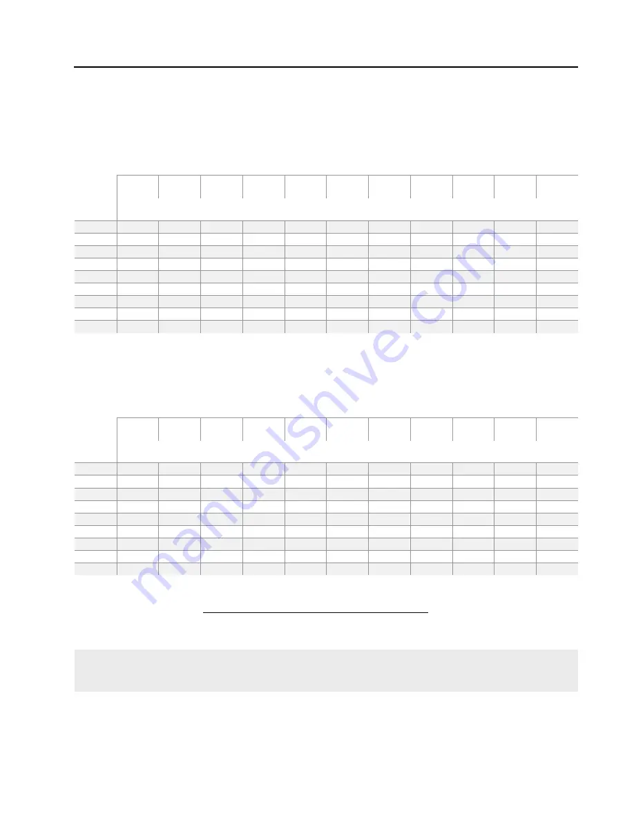
Use these tables to estimate the Intermediate Drive Unit and End Drive Unit speed based on the drive unit
motor output RPM, tire size, and machine voltage. Refer to Figure 81-1.
Estimated Drive Unit Travel Speed Feet/Minute (60 Hz)**
Tire Size
Motor
Output
60 Hz
10R X 22.5 11.2 X 24 11R X 22.5 11R X 24.5
14.9 X 24
Non Directional
14.9 X
24***
16.9 X
24***
18.4 X
26***
11.2 X 38
or Non Directional
12.4R X 38
Valley
Revolution
Feet/Minute
30
5.91
6.11
6.33
6.33
6.95
7.28
7.74
8.17
8.34
8.46
6.96
34
6.70
6.92
7.18
7.18
7.88
8.25
8.77
9.26
9.45
9.59
7.89
37
7.29
7.53
7.81
7.81
8.57
8.98
9.55
10.08
10.28
10.44
8.58
43
8.48
8.75
9.08
9.08
9.96
10.43
11.09
11.71
11.95
12.13
9.97
56
11.04
11.40
11.82
11.82
12.98
13.59
14.45
15.26
15.56
15.79
12.99
68
13.40
13.84
14.36
14.36
15.76
16.50
17.54
18.53
18.90
19.18
15.77
86
16.95
17.50
18.16
18.16
19.93
20.87
22.19
23.43
23.90
24.26
19.95
100
19.71
20.35
21.12
21.12
23.17
24.26
25.80
27.24
27.79
28.21
23.19
136
26.81
27.68
28.72
28.72
31.52
33.00
35.09
37.05
37.80
38.36
31.54
Estimated Drive Unit Travel Speed Feet/Minute (50 Hz)**
Tire Size
Motor
Output
50 Hz
10R X 22.5 11.2 X 24 11R X 22.5 11R X 24.5
14.9 X 24
Non Directional
14.9 X
24***
16.9 X
24***
18.4 X
26***
11.2 X 38
or Non Directional
12.4R X 38
Valley
Revolution
Feet/Minute
25
4.93
5.09
5.28
5.28
5.79
6.07
6.45
6.81
6.95
7.05
5.80
28
5.58
5.77
5.98
5.98
6.57
6.87
7.31
7.72
7.87
7.99
6.57
31
6.08
6.28
6.51
6.51
7.15
7.48
7.96
8.40
8.57
8.70
7.15
36
7.06
7.29
7.57
7.57
8.30
8.69
9.25
9.76
9.96
10.11
8.31
47
9.20
9.50
9.85
9.85
10.81
11.32
12.04
12.71
12.97
13.16
10.82
57
11.17
11.53
11.97
11.97
13.13
13.75
14.62
15.44
15.75
15.98
13.14
72
14.13
14.59
15.13
15.13
16.61
17.39
18.49
19.52
19.92
20.21
16.62
83
16.43
16.96
17.60
17.60
19.31
20.22
21.50
22.70
23.16
23.50
19.33
136
26.81
27.68
28.72
28.72
31.52
33.00
35.09
37.05
37.80
38.36
31.54
Drive Unit Speed(ft/min) = (Tire rolling Circumference x Motor Speed(rpm))
(Gearbox Reduction(52) x 12)
** These speeds are estimates only. Actual speeds will vary according to inflation pressure and field conditions.
Machine speed should be measured after installation to determine the actual performance.
*** Includes turf tires of same nominal size.
Figure 81-1 Estimated Drive Unit Speed Tables
Содержание VRI-iS
Страница 2: ...2 This page was left blank intentionally...
Страница 44: ...This page was left blank intentionally 44 Setup...
Страница 50: ...50 Field Install and Wiring Diagrams VRI iS Power Supply Tower Box Field Install pn 9312421...
Страница 51: ...51 Field Install and Wiring Diagrams VRI iS Power Supply Tower Box Wiring Schematic pn 0999334...
Страница 52: ...52 Field Install and Wiring Diagrams VRI iS GPS Position Tower Box Field Install pn 9312419...
Страница 53: ...53 Field Install and Wiring Diagrams VRI iS GPS Position Tower Box Wiring Schematic pn 0999346...
Страница 82: ...82 Troubleshooting This page was left blank intentionally...
Страница 102: ...102 Parts This page was left blank intentionally...


