Valley Sportsman 8725657 Скачать руководство пользователя страница 14

15 


The O/

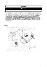
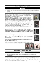
 power switch (O) is located in the upper corner of the Install holes. Attach 

the switch to the side of the steel stand using two nuts, bolts and washers (X). 
NOTE: Be sure O is at the top. (Figure 12) 

Take out the black wire and pass the black,


white and green wires through 

cable sleeve, then insert the cable sleeve into hole site of panel (figure 13). 
Before the wires are connected to the terminals, please do not tighten the cable 
sleeve. Then insert the wire into the holes of switch cover, (figure 13 has took 
out the switch cover, for better showing terminal connection), connect the white 
wire to one side of the overload protector (A1) and the other side connected the 
red wire to the switch in position 1, another black one connected to the switch in 
position 3. Once the wires went through, pull some of black cables through it as 
well. It makes easier to connect the wires to the terminals. Insert the black, white, 
green wires of motor into another hole of switch cover. 

Insert the black, white, green of motor wire into another hole of switch cover. 


Connect the black wire to switch in position 2, connect the white wire to switch in position 
4, and two grounding wires lead to connect the steel side panel by nuts, bolts and  
washers. Grounding logo on the right of switch mounting hole. Tighten the bolts. The X 
Grounding wires connects the steel structure of the machine to the ground

(Figure13)

.


Attach the switch cover (Z) to the steel cabinet with nuts, bolts and washers, and 
tighten the cable bushing (AA) by hand. (Figure 14) 


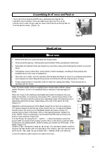
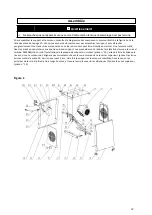
(Figure B1)keep your hands away from the blade edge, please place your hands at  
the inside of baffle. 

 
  (

Figure 

B2)When using mince function, your hand is prohibited to reach into the    

feed inlet, pressing the meat by bar 

                                                  
(

Figure 

B3)When remove the head of meat grinder, keep a safe distance from the 

transmission shaft and no object can be approached  


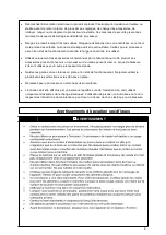
Remove the four socket screws from the table support as described on Page 7 (Figure 3). Then, from 
the left front side of the machine, hold the table in both hands and guide it up onto the two table guide 
wheels (BB) on that side. The wheels should fit the rails which are already attached to the underside  
of the table. Guide the table across the top of the machine to the guide wheels on the opposite side. 
Once the table is in place, reattach the table support. (Figure 15) 

Assembling the Power Switch


WARNING


Attaching the Stainless Steel Table


WARNING


WARNING


Содержание 8725657

Страница 1: ...3 4 HP MEAT PROCESSOR Model 8725657 READ SAVE THESE INSTRUCTIONS...

Страница 2: ...s 8 Meat Processor Specifications 9 Package Contents 10 Parts List 10 Assembly 12 Replacing and Adjusting Saw Blade 13 Assembling the Power Switch 15 Attaching the Stainless Steel Table 15 Assembling...

Страница 3: ...ment This meat processor is to be used for commercial use only Property Specification Component Construction Steel Stainless Steel Weight 110 Pounds Maximum Meat Width 9 7 8 Maximum Meat Thickness 9 7...

Страница 4: ...4 WARNING WARNING CAUTION...

Страница 5: ...condition prior to storage and before re use Use only accessories that are recommended by the manufacturer for use with your product Accessories that may be suitable for one meat processor may create...

Страница 6: ...cing the risk of electric shock See Figure A The grounding prong in the plug is connected through the green wire inside the cord to the grounding system in the meat processor The green wire in the cor...

Страница 7: ...nimum Wire Size Of Extension Cords Nameplate AMPS Cord Length 25 50 100 150 0 6 18 AWG 16 AWG 16 AWG 14 AWG 6 10 18 AWG 16 AWG 14 AWG 12 AWG 10 12 16 AWG 16 AWG 14 AWG 12 AWG 12 16 14 AWG 12 AWG NOT R...

Страница 8: ...Locking Knob 6 Sliding Stainless Steel Table 7 Front Access Door 8 Front Motor Access Panel 9 Rubber Feet 10 Steel Stand 11 Meat Grinder Locking Nut 12 Tube Connector 13 Meat Grinder Intake 14 Stuffer...

Страница 9: ...6 Saw Blade Protection Device 1 B6 Washer 8mm 8 7 Adjustable Support 2 B7 Locking Washer 8mm 28 8 Fence Guide 1 B8 Nut M8 28 9 Fence 1 B9 Bolt M8 16 20 10 Pusher Guide 1 B10 Nut M4 5 11 Pusher 1 B11...

Страница 10: ...11...

Страница 11: ...rs of the stand The feet will help reduce vibration when the saw is in use NOTE When installing the Motor Support Plate Part 20 it must angle toward the front otherwise the motor will not line up prop...

Страница 12: ...alignment of the blade or to replace the blade entirely Figure 6 To center the blade on the wheel loosen the two nuts J until the blade centers onto the Drive Wheel and then retighten the nuts Turning...

Страница 13: ...ng it in the channel Loosening the socket screw T on the Blade Guide will move it toward or away from the blade Finally loosen the socket screw U to move the Bearing V toward or away from the blade Fo...

Страница 14: ...hite wire to switch in position 4 and two grounding wires lead to connect the steel side panel by nuts bolts and washers Grounding logo on the right of switch mounting hole Tighten the bolts The X Gro...

Страница 15: ...attach the fence and pusher to their respective areas Figure 16 Assembling the Fence and Pusher Meat Cutting WARNING If machine has overloaded or blocked disconnect the overload protection switch a n...

Страница 16: ...h Clean the inside of the body as well as the fences table blade and grinder Do not introduce water into the electric motor through the motor vents Do not use a water hose to clean the machine Do not...

Страница 17: ...18...

Страница 18: ...Manuel d instructions PROCESSEUR DE VIANDE 3 4 HP Mod le 1A MS501 LISEZ ET CONSERVEZ CES INSTRUCTIONS...

Страница 19: ...rocesseur de viande 9 Contenu de l emballage 10 Liste de pi ces 10 Assembl e 12 Remplacement et r glage de la lame de scie 13 Assemblage du commutateur d alimentation 15 Fixation de la table en acier...

Страница 20: ...ur de viande ne doit tre utilis que pour un usage commercial Propri t Sp cification Construction de composant Acier acier inoxydable Poids 110Livres Largeur maximale de la viande 9 7 8 paisseur maxima...

Страница 21: ...4 AVERTISSEMENT AVERTISSEMENT...

Страница 22: ...5 ATTENTION...

Страница 23: ...de le r utiliser Utilisez uniquement les accessoires recommand s par le fabricant pour votre produit Les accessoires pouvant convenir un processeur de viande peuvent cr er un risque de blessure s ils...

Страница 24: ...ctricit de l utilisateur r duisant ainsi le risque de choc lectrique Voir la figure A La broche de mise la terre de la fiche est reli e par le fil vert l int rieur du cordon au syst me de mise la terr...

Страница 25: ...le minimale des c bles de prolongateur Plaque signal tique AMPS Longueur 25 50 100 150 0 6 18 AWG 16 AWG 16 AWG 14 AWG 6 10 18 AWG 16 AWG 14 AWG 12 AWG 10 12 16 AWG 16 AWG 14 AWG 12 AWG 12 16 14 AWG 1...

Страница 26: ...tube Apport de hachoir viande Outil Stuffer Bouton de r glage du prot ge lameCover 2 Garde de lame 3 Cl ture 4 Poussoir 5 Bouton de verrouillage du poussoir 6 Table coulissante en acier inoxydable 7 P...

Страница 27: ...de lame de scie 1 B6 Machine laver 8mm 8 7 Support r glable 2 B7 Rondelle de blocage 8mm 28 8 Guide de cl ture 1 B8 crou M8 28 9 Cl ture 1 B9 Boulon M8 16 20 10 Guide du pousseur 1 B10 crou M4 5 11 Po...

Страница 28: ...11...

Страница 29: ...rsque la scie est utilis e REMARQUE Lors de l installation de la plaque de support du moteur pi ce n 20 elle doit tre inclin e vers l avant sinon le moteur ne s alignera pas correctement avec la roue...

Страница 30: ...ue desserrez les deux crous J jusqu ce que la lame soit centr e sur la roue motrice puis resserrez les crous Tourner la roue la main facilite le d placement de la lame Ajustez la vis six pans creux K...

Страница 31: ...the Blade Guide will move it toward or away from the blade Finally loosen the socket screw U to move the Bearing V toward or away from the blade For best results the bearing should be 1 32 away from t...

Страница 32: ...s noir blanc et vert du moteur dans un autre trou du couvercle de l interrupteur Ins rez le fil noir blanc et vert du moteur dans un autre trou du couvercle de l interrupteur Connectez le fil noir au...

Страница 33: ...de la table Guidez la table sur le dessus de la machine vers les roues de guidage du c t oppos Une fois la table en place attachez le support de table Figure 15 La cl ture CC et le poussoir DD ont des...

Страница 34: ...ames mouss es n cessitent un effort suppl mentaire ce qui entra ne leur rupture des d bris volants et des blessures ventuelles pour l utilisateur ou les passants Une fois la coupe effectu e teignez la...

Страница 35: ...table la lame et le moulin N introduisez pas d eau dans le moteur lectrique par les orifices de ventilation du moteur N utilisez pas de tuyau d arrosage pour nettoyer la machine N utilisez pas de solv...

Отзывы: