background image

406

REVO-E Heat pump

4 Function and functional schematics

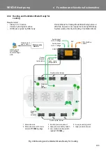
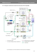
4.4.2 Heating and Ventilation Mode Ready for 

cooling

Requirements:

Clamp 30 / 15 active

Vehicle hybrid system active

HV Mode required by BEA body

Preconditions for Cooling Mode filled shortly before or 
after this, however cool request not sent by BEA body.
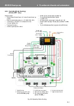
System works primarily in Heating / Ventilation Mode. 

Fig. 404 Heating and Ventilation Mode Ready for Cooling

Double radial blower

Double radial blower

Fresh air
flaps

Sensor
pass. comp.
temperature

Sensor

blow-out

temperature

I/O-A module

Vehicle

Requirement
open / close 

Heating valve

actuator

Fresh air
flaps
actuator

Analog input

HVIL 1 voltage

Analog input

HVIL 2 voltage

CAN interface
vehicle

SC620

4

5

1

2

3

6

7

24V

for hot water 
heat exchanger
ADA

1 Solenoid valve
2 Solenoid valve HGA / actu-

ator 

(in 11123865_only)

3 Suction pressure sensor
4 High pressure safety switch
5 Low pressure safety switch

(

not in 11123865_

)

6 4-way reversing valve
7 High pressure sensor

Содержание REVO-E

Страница 1: ...Rev 06 2019 Id No 11123006A REVO E Heat pump Volvo Workshop Manual AIR CONDITIONING...

Страница 2: ...nctional schematic of the REVO E heat pump 402 4 3 Functional schematic of the REVO E heat pump Volvo 7900 Electric 403 4 4 Work modes of the REVO E heat pump in the Volvo 7900 Electric 404 4 4 1 Heat...

Страница 3: ...701 7 4 Inspection and maintenance 701 7 4 1 Changing the fresh air filter 701 7 4 2 Changing the filter dryer 701 7 4 3 Inspecting the oil level of the compressor 702 7 4 4 Changing the compressor o...

Страница 4: ...7 9 9 1 Remove the duct temperature sensor blow out temperature 907 9 9 2 Install the duct temperature sensor blow out temperature 907 9 9 3 Remove the recirculating air suction temperature sensor pas...

Страница 5: ...mage NOTE Is used when something is to be emphasized 1 4 Symbols 1 5 Additional documentation to be used The use of additional servicing literature is required This is indicated in the workshop manual...

Страница 6: ...rk if the motor is still and the 24V DC power supply as well as the high voltage has been switched off Before starting work on the air conditioning system ensure that the system is voltage free and ma...

Страница 7: ...her temperatures mean higher pressures which may lead to the container exceeding its maximum allowed pressure The rules for pressurized containers stipulate that containers are not to be warmed beyond...

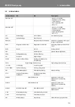
Страница 8: ...Hybrid global chassis application HGA Hei gasabtauung Hot Gas Deicing HV Hochvolt High Voltage HVAC Heizen L ften Klima Heating Ventilation Air Conditioning HVIL High Voltage Interlock Loop High volt...

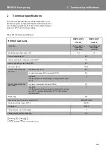
Страница 9: ...s 1st Generation till 2018 Operating range heat pump C 5 3 Cooling capacity kW 1 25 Heating capacity in heat pump mode kW 2 16 Heating capacity coolant circuit kW 40 Air volume m h 6960 Current consum...

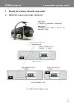
Страница 10: ...bb 1 REVO E HP Installation variants REVO E HP HP Zone 1 For connection to front box REVO E HP 11120816_ 1st generation on solobuses REVO E HP 11123865_ 2nd generation on solobuses und articulated var...

Страница 11: ...valve suction side 16 Expansion valve heating circuit heat pump 17 Safety valve 30bar 18 Bracket refrigerant compressor 19 Refrigerant collector 20 Refrigerant compressor 21 Refrigerant charging valve...

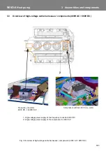
Страница 12: ...mponents 400V AC 600V DC Fig 3 Overview of high voltage cable harnesses components 400V AC 600V DC 1 High voltage power supply of the frequency converter 600V DC 2 High voltage power supply of the com...

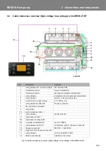
Страница 13: ...harness axial fan 4 way reversing valve 6 solenoid valve hot gas deicing in 11123865_ only 7 wiring harness kit 400V AC frequency converter 8 PE connection compressor 9 compressor 10 suction pressure...

Страница 14: ...cessary discharge refrigerant flow required for cooling The compressor is integrated into the air conditioning system The compressor with patented vibration decou pling design is created using a speci...

Страница 15: ...olute Central parameters for climate heat pump control recognizing icing recognizing low pressure High pressure The high pressure sensor determines the pressure level in the permanent high pressure ar...

Страница 16: ...EVO E Explanations in the following chapters refer largely to the new functions of the heat pump The intelligent controller logic of the SC620 controls further the entire system It communicates with t...

Страница 17: ..._AuxiliaryPowerEnable and supply Fig 401 Functional schematic of the REVO E Analog input HVIL 1 voltage Analog input HVIL 2 voltage CAN interface vehicle SC620 Sensor blow out temperature Sensor pass...

Страница 18: ...radial blowers In Cooling Waste Energy or Gas Charging Mode the double radial blowers are controlled by the SC620 Fig 402 Functional schematic of the REVO E internal Analog input HVIL 1 voltage Analo...

Страница 19: ...heat Mode 8 Waste Energy Mode 9 Gas Charging Mode new mode for heat pump in 11123865_only This is a list of priorities in case several modes are simul taneously required by the BEA body system The SC6...

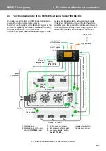
Страница 20: ...ig 403 Heating and Ventilation Mode HV Mode Double radial blower Double radial blower Fresh air flaps Sensor pass comp temperature Sensor blow out temperature I O A module Vehicle Requirement open clo...

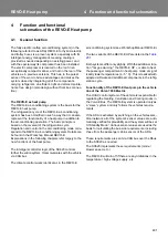
Страница 21: ...lation Mode Ready for Cooling Double radial blower Double radial blower Fresh air flaps Sensor pass comp temperature Sensor blow out temperature I O A module Vehicle Requirement open close Heating val...

Страница 22: ...entilation Mode Ready for Heat Pump Double radial blower Double radial blower Fresh air flaps Sensor pass comp temperature Sensor blow out temperature I O A module Vehicle Requirement open close Heati...

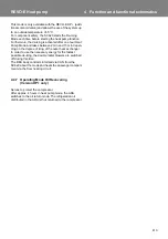
Страница 23: ...r to cool down the air in the passenger cabin to the Delta T value requested by the BEA Body Fig 406 Cooling Mode Analog input HVIL 1 voltage Analog input HVIL 2 voltage CAN interface vehicle SC620 Se...

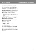
Страница 24: ...mperature to be reached is given by the difference of the external temperature and the T required by the BEA body Example of T 7 Kelvin Tpassenger cabin Texternal 35 C T 7K Tpassenger cabin 28 C This...

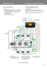
Страница 25: ...ody D_CabinHeatpumpReq signal sent by BEA body Fig 407 Heat Pump Mode Analog input HVIL 1 voltage Analog input HVIL 2 voltage CAN interface vehicle SC620 Sensor blow out temperature Sensor pass comp t...

Страница 26: ...ol the speed of the double radial blowers axial fans Activation and speed setting of the compressor via frequency converter In Heat Pump Mode the BEA body is not able to influence the speed of the dou...

Страница 27: ...ailable to BEA body D_CabinHeatpumpReq signal sent by BEA body Fig 408 Operating Mode De Icing Analog input HVIL 1 voltage Analog input HVIL 2 voltage CAN interface vehicle SC620 Sensor blow out tempe...

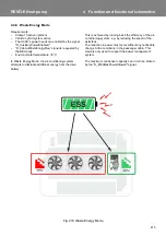
Страница 28: ...2 min and 15 min depen ding on the degree of icing of the outer heat exchanger In order to use the necessary energy for the fastest possible de icing the double radial blowers are switched off during...

Страница 29: ...ing in reheat mode is carried out via the water heat exchangers installed in the system The heat pump function can not do this The maximum condenser capacity can be limited by the D_ElAcMaxPowerAllowe...

Страница 30: ...aste Energy Mode the air conditioning system attempts to dissipate additional energy from the drive battery This is achieved by running back the efficiency of the air conditioning system e g by reduci...

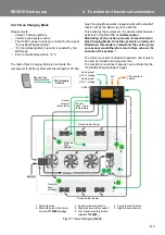
Страница 31: ...ystem is normally not filled when this mode is started and the suction pres sure sensor would therefore read a false value in the vacuum of the system The mode is not part of standard operation and is...

Страница 32: ...the heat pump mode as a condenser and the condenser works as an evaporator Additional components such as a modified pipe circuit various check valves and a further expansion valve support the circulat...

Страница 33: ...Cooling Mode High pressure area charging phase Low pressure area suction side Liquid phase Outer heat exchanger Inner heat exchanger passenger compartment Expansion valve Filter dryer Receiver Check v...

Страница 34: ...Heat Pump Mode High pressure area charging phase Low pressure area suction side Liquid phase Outer heat exchanger Inner heat exchanger passenger compartment Expansion valve Filter dryer Receiver Check...

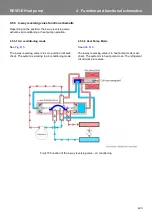
Страница 35: ...pump operation 4 5 3 1 Air conditioning mode See Fig 415 The 4 way reversing valve is in zero position not swit ched The system is working in air conditioning mode 4 5 3 2 Heat Pump Mode See Abb 416...

Страница 36: ...421 REVO E Heat pump 4 Function and functional schematics Abb 416 Function of the 4 way reversing valve Heat Pump Mode...

Страница 37: ...tside temperature of 5 C Abb 417 Refrigerant circuit function schematic of the heat pump with hot gas de icing 11123865_ High pressure area charging phase Outer heat exchanger Inner heat exchanger pas...

Страница 38: ...ances 5 2 3 Why the desired conditions are not reached when testing pressure If deviations from the desired conditions are determined when testing the pressure the following may have caused this Press...

Страница 39: ...for these reasons corrosion on the plugs loose contact crimping errors on the plugs or pins corrosion on lines and fuses corrosion on the battery poles damage to the line insulation ATTENTION Search...

Страница 40: ...ctive 03 10913 PWM double radial blower defective 04 10914 24V power supply too low 05 11554 External temperature signal not received 10s 06 11555 600V system status not received 10s 07 10917 Temperat...

Страница 41: ...nesses according to wiring plan Force control of system via DCT test mode Active with cooling Actions Replace SC620 Replacing double radial blowers NOT necessary F04 24V power supply too low System be...

Страница 42: ...s replace cable harness Measured values on cable harness SC620 side OK replace SC620 F10 Temperature of recirculated air passenger cabin too low T 40 C System behavior Limited cooling functionality Sy...

Страница 43: ...value 0 5bar compressor off that means below the threshold low pressure error entry F12 F18 Necessary inspections Sensor values using DCT operating 2 bar Check pressure with pressure gauge and calibra...

Страница 44: ...ssor does not start Red LED of frequency converter is blinking Note No common problem of the frequency converter Necessary inspections Sensor values using DCT Only relevant in connection with other er...

Страница 45: ...entation There are two options for the diagnosis of the frequency converter 1 MMI handheld control device This is sufficient for reading the fault memory but without precise information about the time...

Страница 46: ...ntact crimping errors etc and repair as needed Inspect plug contacts for corrosion and proper seat ing repair as needed Visually examine all electric lines high and low volt age for abrasion 5 7 Diagn...

Страница 47: ...Lines without color information white Illustrations are generally without power or pressure 6 1 Electrical fuses REVO E Heat Pump 6 2 Wiring diagram REVO E HP 11120816 Fig 601 pages 1 6 includes the w...

Страница 48: ...602 REVO E Heat pump 6 Wiring plan Fig 601 Wiring diagram for REVO E HP Sheet 1 These fans will not be used in short run from SP7 and SP8 PWM signal see sheet 5...

Страница 49: ...603 REVO E Heat pump 6 Wiring plan Fig 601 Wiring diagram for REVO E HP Sheet 2 from X850 1 and SP7 PWM signal see sheet 5 Condenser cable harness This fan will not be used in short run...

Страница 50: ...604 REVO E Heat pump 6 Wiring plan Fig 601 Wiring diagram for REVO E HP Sheet 3 SC600 Interface X133 6 with 10A Fuse SC620...

Страница 51: ...605 REVO E Heat pump 6 Wiring plan Fig 601 Wiring diagram for REVO E HP Sheet 4...

Страница 52: ...606 REVO E Heat pump 6 Wiring plan Fig 601 Wiring diagram for REVO E HP Sheet 5...

Страница 53: ...ndenser Fan PWM 2 Electromagnetic valve Evaporator Blower PWM 3 LP HP Drive Error Fresh Air Flap 4 HVIL detect 1 in Fresh Air Flap 5 HVIL detect 2 out WV 6 Analog Ground Press Sensor WV 7 Pressure Sen...

Страница 54: ...608 REVO E Heat pump 6 Wiring plan 6 3 Wiring diagram REVO E HP 11123865 Fig 602 pages 1 6 includes the wiring diagram for the REVO E HP...

Страница 55: ...609 REVO E Heat pump 6 Wiring plan Fig 602 Wiring diagram for REVO E HP Sheet 1...

Страница 56: ...610 REVO E Heat pump 6 Wiring plan Fig 602 Wiring diagram for REVO E HP Sheet 2...

Страница 57: ...611 REVO E Heat pump 6 Wiring plan Fig 602 Wiring diagram for REVO E HP Sheet 3...

Страница 58: ...612 REVO E Heat pump 6 Wiring plan Fig 602 Wiring diagram for REVO E HP Sheet 4 In REVO E HP only...

Страница 59: ...613 REVO E Heat pump 6 Wiring plan Fig 602 Wiring diagram for REVO E HP Sheet 5...

Страница 60: ...ser Fan PWM 2 Electromagnetic valve Evaporator Blower PWM 3 LP HP No Error Fresh Air Flap 4 HVIL detect 1 in Fresh Air Flap 5 HVIL detect 2 out 4WV 6 Analog Ground Press Sensor 4WV 7 Pressure Sensor R...

Страница 61: ...00V DC including HVIL connector No Designation Configura tion Cable color 1 L1 DC network Red 2 L3 DC network Blue 3 HVIL in vehicle X61 Pin 1 White 4 HVIL out of vehicle X61 Pin 2 Brown 5 HVIL in sys...

Страница 62: ...when connecting the PE line the order of the individual parts must be maintained Fig 605 Fig 604 Voltage output 400V AC 1 Connection for PTC sensor e motor for compressor 2 Cable connection for 400V...

Страница 63: ...n 2 Cable gland 3 Cable gland lock nut 4 Position marking cable 5 Phase connections for 400V AC 3 6 Connection for PTC sensor for electrical motor The position marking cable must be secured with lock...

Страница 64: ...e air conditioning system and prop up with rods attached to cover Remove the coil of the solenoid valve and replace with permanent magnet Siphon refrigerant via high and low pressure connec tions on t...

Страница 65: ...bed in 7 4 Always change the compressor oil when conducting servicing or repair work on the compressor Open the oil filling screw Fig 702 siphon out the old oil and feed in the new oil The amount of o...

Страница 66: ...voltage tester CAT IV suitable for HV systems Fig 603 Chap 6 4 8 3 2 Refrigeration section When working on the refrigerant circuit the rules for eva cuating and filling the REVO E apply Replace the s...

Страница 67: ...cover remove the grounding cable 2 Disconnect the electrical connections of the frequency converter Check the connections L1 and L3 Fig 603 are voltage free using a suitable voltage tester CAT IV Remo...

Страница 68: ...he collar of the plate will dip into opening in the bottom of the heat sink of the frequency converter Inspect the positioning of the centering cone of the fastening screws Attach the frequency conver...

Страница 69: ...en lock nuts 3 Fig 606 of the cable glands for the 400V AC cable and pull the cable out of the terminal box Fig 804 exemplarily 1 2 3 4 1 Protective cover of compressor 2 Torx screws 6 3 High pressure...

Страница 70: ...hat hold the mounting bracket and remove mounting bracket Separate grounding cable by pulling out ring screws 7 from compressor housing screw ring screws back in 4 Removing compressor Lift compressor...

Страница 71: ...ing the air conditioning system see 7 4 4 Note the minimum and maximum oil level Check and adjust as needed the oil level of the air condi tioning system after commissioning 8 4 3 Install the compress...

Страница 72: ...s NOTE Please always comply with given torque Other wise the foam will lose its absorbent affect This causes the transference of vibration to the bus roof Install mounting parts of the compressor in t...

Страница 73: ...5 2 Install the 600V DC cable Install cable in the opposite order Connecting the clamps see 6 4 ATTENTION The cable must not touch any sharp edges abra sion hazard 8 5 3 Remove the 400V AC cable The c...

Страница 74: ...16 Lay the 400V AC cable according to Fig 815 and Fig 817 and attach to the traverses and compressor pan ATTENTION The cable cannot touch any sharp edges abra sion hazard Connect the 400V AC cable to...

Страница 75: ...ssor Close openings of components of the refrigerant circuit with suitable plugs presents water absorption by the refrigerant oil Follow up work Exchange filter dryers Evacuation the air conditioning...

Страница 76: ...n reverse order Thereby the gaskets of the refrigerant circuit are to be replaced Do the final work according to 9 3 Fig 901 exemplarily 1 Frequency inverter design cover 2 Compressor design cover 3 P...

Страница 77: ...902 Positions of expansion valves and the associated contact sensors Contact sensor expansion valve outer heat exchanger Contact sensor expansion valve left hand inner heat exchanger Expansion valve...

Страница 78: ...lve 9 4 3 Install an expansion valve Apply refrigerator oil to sealing rings Place the expansion valve 2 into the location of installation and attach with cap nuts Attach thermostat sensor 1 with hold...

Страница 79: ...lation and attach with cap nuts While doing so prevent dryer filter from twisting with suitable tool Attach retaining clamp Conduct follow up work according to 9 3 9 6 Receiver removal installation 9...

Страница 80: ...ing SCT components test 9 7 3 Remove an axial fan Remove the electrical connection to the housing 4 from the holder 6 Remove attachment screws 5 Remove housing 4 9 7 4 Install an axial fan Insert hous...

Страница 81: ...temperature Position to the right side before the first double radial blower 1 Fig 908 Loosen electrical connection on the plug Unscrew sensor from holder 9 9 2 Install the duct temperature sensor bl...

Страница 82: ...leak test is 17 bar since otherwise the suction pressure sensor will become damaged 9 11 High pressure sensor removal installation There is a valve insert built into the soldering support of the high...

Страница 83: ...Disconnect the pressure line at the SMA connection from the compressor and remove pressure line 9 13 2 Install the pressure line Put pressure line including new seals refrigerator oil applied into ins...

Страница 84: ...nut 3 ATTENTION Always ensure the plug points with the cable side down in order to avoid water entry into the plug 9 14 3 Remove the screw in valve Conduct preparation work according to 9 3 Remove co...

Страница 85: ...34 10 flange seal oval 11117795A 3 screw M10x110 suction gas line compressor 50 10 flange seal oval 11117795A 4 union nut SW27 outer heat exchanger 25 10 O ring 14 x 1 78 80641A 5 union nut SW27 filte...

Страница 86: ...ne 10 10 O ring 4 48 x 1 78 1103522B 12 union nut SW22 expansion valve outlet 25 10 O ring 10 6 x 1 78 80640A 13 union nut SW14 sensor high pressure 10 10 O ring 7 65 x 1 78 80812A 14 union nut SW27 l...

Страница 87: ...memos...

Страница 88: ...ial Vehicles Germany GmbH Friedrichshafener Str 7 Tel 49 0 8105 7721 0 Fax 49 0 8105 7721 889 82205 Gilching Germany www valeo thermalbus com service valeobus valeo com Valeo Thermal Commercial Vehicl...

Отзывы: