804
REVO-E Heat pump
8 Removal/ installation of components (high-volt. syst.)
8.4
Refrigerant compressor removal/ installation
8.4.1 Remove the compressor
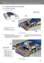
1. Preparation work, see
2. Disconnecting the electrical lines
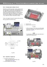
• Open the terminal box of the compressor using the
special key (attached to the compressor).
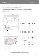
• Loosen electrical connections, see
.
• Loosen lock nuts (3,
) of the cable glands
for the 400V AC cable and pull the cable out of the
terminal box.
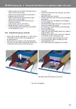
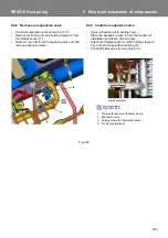
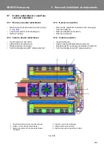
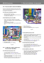
Fig. 804 (exemplarily)
1
2
3
4
1
Protective cover of compressor
2
Torx screws (6)
3
High-pressure / fluid connection
4
Low-pressure / suction connection
See torque table
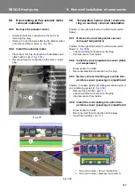
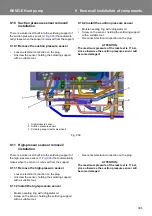
Fig. 805 (exemplarily)
1
Cable gland for 400V AC
cable
2
Screws for retaining plate of
compressor pan (4x)
3
Screws for suction supply for
compressor (2x)
4
Screws for pressure plate on
compressor pan (4x)
5
Screws for suction pipe (2x)
1
2
3
4
5
See torque table
Содержание REVO-E
Страница 1: ...Rev 06 2019 Id No 11123006A REVO E Heat pump Volvo Workshop Manual AIR CONDITIONING...
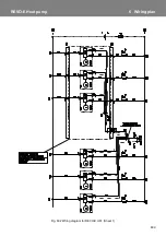
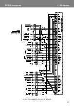
Страница 51: ...605 REVO E Heat pump 6 Wiring plan Fig 601 Wiring diagram for REVO E HP Sheet 4...
Страница 52: ...606 REVO E Heat pump 6 Wiring plan Fig 601 Wiring diagram for REVO E HP Sheet 5...
Страница 55: ...609 REVO E Heat pump 6 Wiring plan Fig 602 Wiring diagram for REVO E HP Sheet 1...
Страница 56: ...610 REVO E Heat pump 6 Wiring plan Fig 602 Wiring diagram for REVO E HP Sheet 2...
Страница 57: ...611 REVO E Heat pump 6 Wiring plan Fig 602 Wiring diagram for REVO E HP Sheet 3...
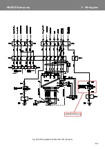
Страница 58: ...612 REVO E Heat pump 6 Wiring plan Fig 602 Wiring diagram for REVO E HP Sheet 4 In REVO E HP only...
Страница 59: ...613 REVO E Heat pump 6 Wiring plan Fig 602 Wiring diagram for REVO E HP Sheet 5...
Страница 87: ...memos...

