504
REVO-E Heat pump
5 Troubleshooting
5.5
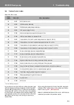
Error codes
F01 ECU internal error
System behavior
– System not functioning & display off (GH) / LED not
blinking
or
– Display shows 'boot’ and ‘Err code’
Necessary inspections
– Test system using DCT
– Inspect the power supply of the SC620
Actions
– Replace SC620
F02 PWM axial fan defective
System behavior
– Refrigerant compressor stops during Cooling
Mode
– Axial fans do not run despite Cooling Mode being
activated
– System in Ventilation Mode despite cooling
demand from vehicle active
Necessary inspections
– Inspect axial fans. Use the DCT from the diagnos-
tic case.
– Inspect cable harnesses according to wiring plan
– Force control of system via DCT test mode "Active
with cooling”
Actions
– Replace SC620
– Replacing axial fans NOT necessary
F03 PWM double radial blowers defective
System behavior
–
Failure of all double radial blowers in system
–
Refrigerant compressor stops during Cooling Mode
–
System in Ventilation Mode despite cooling being re-
quired in vehicle
Necessary inspections
–
Inspect double radial blowers. Use the DCT from the
diagnostic case.
–
Inspect cable harnesses according to wiring plan
–
Force control of system via DCT test mode "Active
with cooling”
Actions
–
Replace SC620
–
Replacing double radial blowers NOT necessary
F04 24V power supply too low
System behavior
–
double radial blowers not functioning
–
Cooling Mode not functioning
–
Power supply < 22V/ >10s
Necessary inspections
–
Inspect 24V power supply (error active up to power
supply >28V)
Actions
–
Bus servicing necessary
F05 External temperature signal not received >10s
System behavior
–
Limited cooling function
–
System in Cooling Mode
Necessary inspections
–
Inspect external temperature sensor of bus
–
Inspect CAN bus communication
Actions
–
according to Volvo documentation
F06 600V system status not received >10s
System behavior
–
Limited cooling functionality
–
System in Cooling Mode
Necessary inspections
–
Inspect system with DCT component test
–
Inspect CAN bus communication
Actions
–
according to Volvo documentation
F07 Temperature of air duct / outlet temperature too
high (T
≥
105°C)
System behavior
–
Limited heating functionality
Necessary inspections
–
Sensor values using DCT
–
Sensor resistance on the sensor / to the SC620 plug
(SC620 not connected) according to wiring plan
10kOhm 12.5kOhm
15.7kOhm
25°C
20°C
15°C
–
Voltage present on sensor when SC620 and sensor
plug connected
1.36V
1.5V
1.7V
25°C 20°C
15°C
Содержание REVO-E
Страница 1: ...Rev 06 2019 Id No 11123006A REVO E Heat pump Volvo Workshop Manual AIR CONDITIONING...
Страница 51: ...605 REVO E Heat pump 6 Wiring plan Fig 601 Wiring diagram for REVO E HP Sheet 4...
Страница 52: ...606 REVO E Heat pump 6 Wiring plan Fig 601 Wiring diagram for REVO E HP Sheet 5...
Страница 55: ...609 REVO E Heat pump 6 Wiring plan Fig 602 Wiring diagram for REVO E HP Sheet 1...
Страница 56: ...610 REVO E Heat pump 6 Wiring plan Fig 602 Wiring diagram for REVO E HP Sheet 2...
Страница 57: ...611 REVO E Heat pump 6 Wiring plan Fig 602 Wiring diagram for REVO E HP Sheet 3...
Страница 58: ...612 REVO E Heat pump 6 Wiring plan Fig 602 Wiring diagram for REVO E HP Sheet 4 In REVO E HP only...
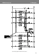
Страница 59: ...613 REVO E Heat pump 6 Wiring plan Fig 602 Wiring diagram for REVO E HP Sheet 5...
Страница 87: ...memos...

