background image

Operation 6

0020230535_05 ecoFIT pure Installation and maintenance instructions

15

Conditions

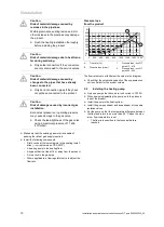
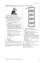
: When connecting a control (230 V).

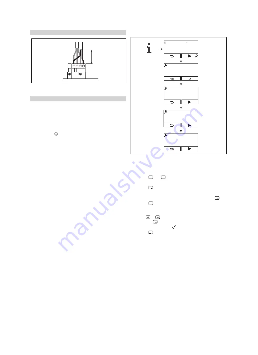
≤ 30 mm

N

L

X1

230V~

RT

Connect the control to the main plug.

Remove the bridge from the plug

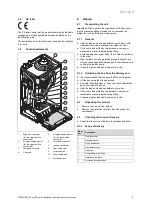
24V=RT

.

Conditions

: 230 V 3-wire connection

Connect the boiler only using the set with article number
0020244337 (Installation Kit, 3-wire, Vaillant).

When connecting, observe the instructions for the
set.

Connect the control to the main plug X1.

Terminal assignment: L

Phase, N

neutral con-

ductor,

earth

Draw the end user's attention to the fact that the follow-
ing features are present with this installation type.

The frost protection function is deactivated. If the
product is installed in a room where there is a risk
of frost and it has not been protected by a room ther-
mostat, install an additional frost protection thermo-
stat.

The pump programmes are not active.

If the product is switched off, the display is switched
off.

Each time the unit is started, the fan runs for
20 seconds.

Residual heat in the heating return may result in the
product blocking the burner for 10 minutes.

4.

Close the electronics box.

6

Operation

6.1

Operating concept

The operating concept and the display and setting facilities
of the operator level are described in the operating instruc-
tions.

An overview of the display and setting options in the installer
level can be found in the section "Overview of the installer
level". (

Page 15)

6.2

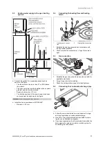
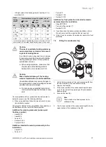
Installer level overview

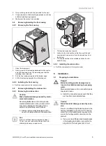
S.31

Code

D.---

PF

P.--

D F

--/--

DP

6.3

Calling up the installer level

1.

Only call up the installer level if you are a competent
person.

2.

Press

and

("i") at the same time.

S.xx

appears in the display (current unit status).

3.

Press

to access the installer level.

Code

and

--

appear in the display.

4.

Set the value

17

(code) and confirm by pressing

.

5.

Press

to access the check programmes

(P)

and the

fault codes

(F)

and to return to the diagnostics codes

(D)

.

6.

Use

or

to set the required value and confirm by

pressing

.

7.

Confirm by pressing ( ).

8.

Press

to cancel a setting or exit the installer level.

6.4

Live Monitor (status codes)

Menu

Live monitor

Status codes in the display provide information on the pro-
duct's current operating status.

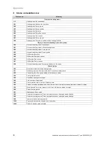
Status codes

Overview (

Page 30)
Содержание ecoFIT pure 412

Страница 1: ...allation and maintenance instructions ecoFIT pure 412 435 GB IE Publisher manufacturer Vaillant GmbH Berghauser Str 40 D 42859 Remscheid Tel 492191 18 0 Fax 492191 18 2810 info vaillant de www vaillan...

Страница 2: ...7 4 Filling the condensate trap 17 7 5 Switching on the product 18 7 6 Filling the heating installation 18 7 7 Checking the gas flow rate 18 7 8 Checking and adjusting the gas settings 18 7 9 Checkin...

Страница 3: ...accompanying operating installation and servicing instructions for the product and any other system compon ents installing and fitting the product in accord ance with the product and system approval c...

Страница 4: ...sub stances such as petrol paper or paint 1 3 8 Risk of death from electric shock There is a risk of death from electric shock if you touch live components Before commencing work on the product Disco...

Страница 5: ...lation and maintenance instructions 5 1 3 13 Risk of material damage caused by using an unsuitable tool Use the correct tool 1 4 Regulations directives laws standards Observe the national regulations...

Страница 6: ...age and promote the Scheme Benchmark is managed and promoted by the Heating and Hotwater Industry Council For more information visit www centralheating co uk 3 2 Compartment Ventilation The boilers ar...

Страница 7: ...t If the unit is being lifted by two persons ensure your movements are coordinated during lifting Avoid bending your upper body do not lean forwards or to the side Wear suitable non slip protective gl...

Страница 8: ...d D 600 mm Dimension A can be reduced to 20 mm if there is a removable surface above the product 4 5 1 Clearance from combustible components It is not necessary to maintain a clearance between the pro...

Страница 9: ...aks Always remove only one side section never both side sections at the same time Note If there is sufficient lateral clearance at least 70 mm you can remove the side section to fa cilitate maintenanc...

Страница 10: ...ed Install the following components Drain cocks at the lowest points in the heating install ation current version of BS 2879 A heating pump in the heating flow A bypass that is at least 1 5 m away fro...

Страница 11: ...ing flow and heating return 2 1 1 Heating return connec tion 2 Heating flow connection 1 Establish the heating connections in accordance with the applicable standards 2 Check whether the connections P...

Страница 12: ...the pipe wall which can freeze and build into a larger ice plug For any installation the condensate must be free flowing and not be possible for air back pressure to prevent wa ter flow As with other...

Страница 13: ...flue gas installation The combustion air must not be taken from the installation site Caution Risk of poisoning due to escaping flue gas Mineral oil based greases can damage the seals Instead of grea...

Страница 14: ...ection 3 A 5 Open the electronics box Page 13 6 Observe the routing of the power supply cable 1 in the electronics box in order to guarantee that there is no strain 30 mm N L X1 230V RT 7 Carry out th...

Страница 15: ...s Residual heat in the heating return may result in the product blocking the burner for 10 minutes 4 Close the electronics box 6 Operation 6 1 Operating concept The operating concept and the display a...

Страница 16: ...has been factory tested and is preset for operation with the gas group indicated on the iden tification plate The product is only authorised to be operated with natural gas Check the information about...

Страница 17: ...ction agents biocides or seal ants No incompatibility with our products has been detected to date with proper use of the following additives When using additives follow the manufacturer s instruc tion...

Страница 18: ...sioning checklist 7 8 Checking and adjusting the gas settings Only a qualified competent person is authorised to imple ment the settings on the gas valve assembly Each destroyed tamper proof seal must...

Страница 19: ...s any CO or CO2 7 If you cannot eliminate the damage do not start up the product 7 8 3 Checking the CO content 1 Start up the product with check programme P 01 Overview of the check programmes Page 16...

Страница 20: ...oubleshooting 10 1 Eliminating faults If fault messages F xx appear eliminate the fault after referring to the table in the appendix or using the check programmes Page 16 Overview of fault codes Page...

Страница 21: ...s 10 6 1 Replacing the burner 1 Remove the gas air mixture unit Page 23 2 Remove the burner seal 3 Remove the burner 4 Install the new burner complete with new seal on the heat exchanger 5 Install the...

Страница 22: ...duct is leak tight Page 19 11 Inspection and maintenance 11 1 Using original seals If you replace components use only the enclosed original seals additional sealing materials are not required 11 2 Obs...

Страница 23: ...ting the CO value Great Britain front casing on front casing off Natural gas G20 CO at full load 9 2 0 2 Set for Wobbe index W 14 09 kW h m O at full load 4 5 1 8 vol CO at full load 250 ppm CO CO 0 0...

Страница 24: ...face of the burner for damage If you see any damage replace the burner 11 8 Checking the ignition electrode 1 2 3 4 5 1 Disconnect the connection 2 and the earthing cable 1 2 Remove the fixing screws...

Страница 25: ...pection and maintenance work 1 Check the gas connection pressure gas flow pressure Page 18 2 Check the CO content Page 22 11 12 Checking the product for leak tightness Check that the product is leak t...

Страница 26: ...tions Annually 9 If the gas flow rate lies outside of the tolerances specified in these in structions eliminate the fault in accordance with the regulations and the current technology Annually 10 Chec...

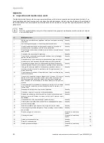
Страница 27: ...table d 02 Burner anti cycling time in heating mode 2 60 min 1 20 Adjustable d 04 Water temperature in the cylinder Current value Not adjustable d 05 Determined heating flow set target temperature Cur...

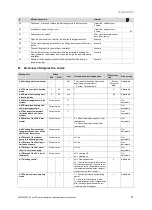
Страница 28: ...xternal solenoid valve 6 External fault message 7 Solar pump omitted 8 eBUS remote control 9 Legionella protection pump 10 Solar valve 2 Adjustable d 31 Automatic filling device 0 2 0 Manual 1 Semi au...

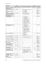
Страница 29: ...ata Adjustable d 78 DHW max flow temperat ure 50 80 1 Adjustable d 80 Running time in heating mode Current value h Not adjustable d 81 Running time in DHW mode Current value h Not adjustable d 82 Numb...

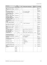
Страница 30: ...errun S 27 DHW mode Pump overrun S 28 Hot water handling mode Temporary shutdown of the burner Other displays S 30 Room thermostat is blocking heating mode S 31 No heating demand Summer mode eBUS cont...

Страница 31: ...ignition cable ignition plug ignition electrode defective ionisation current interrupted cable electrode incorrect earthing of product electronics defective F 29 Failure during operation Re ignition u...

Страница 32: ...When the burner starts the temperature change registered at the flow and or return temperature sensor is non existent or too small Insufficient water in product Flow or return temperature sensor not...

Страница 33: ...1 X106 X32 X12 X35 X1 RT X21 L N L N 1 5 eBUS Burner off X106 M 4 3 2 1 N L 24V 230V 24V 230V 2 7 9 1 4 3 5 6 10 11 12 8 1 Main PCB 2 Interface PCB 3 Control system 4 Temperature sensor on the heating...

Страница 34: ...T X1 X106 X32 X12 X35 X1 RT X21 L N L N 1 5 eBUS Burner off X106 M 4 3 2 1 N L 24V 230V 24V 230V 2 7 9 1 4 3 5 6 10 11 12 8 1 Main PCB 2 Interface PCB 3 Control system 4 Temperature sensor on the heat...

Страница 35: ...water pipes 75 mm E Below eaves 200 mm F Below balconies or car port roofs 200 mm G From vertical wastewater pipes or down pipes 150 mm H From external or internal corners 200 mm I Above floors roofs...

Страница 36: ...his manual 1 Dimensions D E F and G These clearances may be reduced to 25 mm without affecting the performance of the boiler In order to ensure that the con densate plume does not affect adjacent surf...

Страница 37: ...ntenance instructions 37 H Commissioning Checklist Heating and Hotwater Industry Council HHIC www centralheating co uk Benchmark Commissioning and Servicing Section It is a requirement that the boiler...

Страница 38: ...th the appropriate Building Regulations and then handed to the customer to keep for future reference GAS BOILER SYSTEM COMMISSIONING CHECKLIST CONTROLS Optimum start control Fitted Fitted Fitted Fitte...

Страница 39: ...g system is serviced regularly and that the appropriate Service Interval Record is completed Service Provider SERVICE RECORD SERVICE 01 AND AND SERVICE 02 AND AND SERVICE 03 AND AND SERVICE 04 AND AND...

Страница 40: ...ow to set boiler to minimum rate contact Technical Helpline for advice CHECK CO AND COMBUSTION RATIO AT MINIMUM RATE With boiler still set at minimum rate insert analyser probe into flue gas sampling...

Страница 41: ...d 4 0 at 50 30 C 3 06 l h 3 65 l h Technical data G20 power loading G20 VU 126 6 3 OV H GB VU 156 6 3 OV H GB VU 186 6 3 OV H GB VU 256 6 3 OV H GB Maximum heat output 12 kW 15 kW 18 kW 25 kW Effectiv...

Страница 42: ...063CP3646 CE 0063CP3646 Flue gas mass rate in heating mode at P min 2 08 g s 2 08 g s 2 31 g s 2 81 g s Flue gas mass rate in heating mode at P max 5 5 g s 6 9 g s 8 3 g s 11 5 g s Flue gas mass rate...

Страница 43: ...C at P min 56 56 Flue gas temperature 50 C 30 C at P max 60 62 Flue gas temperature 50 C 30 C at P min 37 37 Flue gas temperature in hot water handling mode 75 75 Flue gas temperature when over heati...

Страница 44: ...0020230535_05 VU 306 6 3 OV H GB VU 356 6 3 OV H GB Electric connection 230 V 50 Hz 230 V 50 Hz Built in fuse slow blow T2 2A 250V T2 2A 250V Max electrical power consump tion 44 W 50 W Standby elect...

Страница 45: ...Handing over to the end user 20 I Identification plate 6 If you smell flue gas 4 If you smell gas 3 Inspection work 22 Installation site 4 Installer level 15 Installer level calling up 15 Installing...

Страница 46: ......

Страница 47: ......

Страница 48: ...e DE56 1JT Telephone 0330 100 3461 info vaillant co uk www vaillant co uk These instructions or parts thereof are protected by copyright and may be reproduced or distributed only with the manufacturer...

Отзывы: