72
Installation and maintenance instructions 0020297933_07
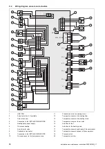
5.14.6 Removing the air inlet grille
D
C
3×1
A
2×2
3×1
B
E
2×1
1
2
1.
Disconnect the electrical connection to the temperature
sensor
(1)
.
2.
Remove the two cross-members
(2)
as shown in the
figure.
3.
Remove the air inlet grille as shown in the figure.
5.14.7 Installing the casing sections
1.
When installing, carry out the steps for removal in re-
verse.
2.
To do this, follow the figures for the removal
(
6
Hydraulics installation
6.1
Installation type: Direct connection or
system separation
In the case of a direct connection, the outdoor unit is hy-
draulically connected directly to the indoor unit and the heat-
ing installation. In this case, if there is frost, there is a risk
that the outdoor unit will freeze.
In the case of a system separation, the heating circuit is sep-
arated into a primary and a secondary heating circuit. In this
case, the separation is implemented using an optional inter-
mediate heat exchanger, which is positioned in the indoor
unit or in the building. If the primary heating circuit is filled
with a water/frost protection mixture, the outdoor unit is pro-
tected against freezing in the case of frost or a power cut.
6.2
Guaranteeing the minimum circulation water
volume
In heating installations that are equipped primarily with ther-
mostatic or electrically controlled valves, a constant and suf-
ficient flow through the heat pump must be ensured. When
designing the heating installation, the minimum circulation
water volume of heating water must be guaranteed.
6.3
Requirements for hydraulic components
Plastic pipes that are used for the heating circuit between the
building and the product must be diffusion-tight.
Pipelines that are used for the heating circuit between the
building and the product must have UV- and high-temperat-
ure-resistant thermal insulation.
6.4
Preparing the hydraulics installation
1.
Flush the heating installation thoroughly before con-
necting the product in order to remove any possible
residue from the pipelines.
2.
If you carry out soldering work on connectors, carry this
out while the associated pipelines have not yet been
installed on the product.
3.
Install a line strainer in the pipeline for the heating re-
turn.
6.5
Routing pipelines to the product
1.
Route the pipelines for the heating circuit from the
building, through the wall duct and to the product.
Validity:
Floor installation
▶
Route the pipelines through a suitable safety pipe in
the ground, as shown in the example in the figure.
▶
You can find the dimensions and clearances in the
set-up instructions for the accessories (pre-installation
jig, installation set).


