


52
Operating instructions 0020297933_07
4.1.4
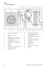
Protective zone for wall installation in front
of a building wall
C
D
A
B
A
2100 mm
B
3100 mm
C
200 mm/250 mm
D
1000 mm
The protective zone below the product extends as far as the
floor.
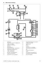
4.1.5
Protective zone for wall installation in a
building corner
B
C
D
E
F
G
A
A
2100 mm
B
2600 mm
C
200 mm/250 mm
D
500 mm
E
1000 mm
F
500 mm
G
1800 mm
The protective zone below the product extends as far as the
floor.
4.1.6
Protective zone for flat-roof installation
A
A
1000 mm
4.2
Design of the condensate discharge
The condensate that accumulates can be guided into a
sewer, pump sump or soakaway via a downpipe, gully,
balcony run-off or roof run-off. Open gullies or downpipes
within the protective zone do not pose any safety risk.
For all installation types, you must ensure that any condens-
ate that accumulates is discharged frost-free.
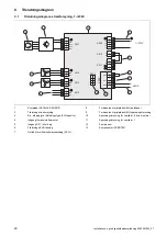
4.2.1
Design of the condensate discharge for
ground installation
For the ground installation, the condensate must be dis-
charged via a downpipe into a gravel bed which is located
in the frost-free area.
10
0
100
A
For a region with ground frost, dimension A is
≥
900 mm
and, for a region without ground frost, it is
≥
600 mm.
The downpipe must flow into a sufficiently large gravel bed
so that the condensate can trickle away freely.
To prevent the condensate from freezing, the heating wire
must be threaded into the downpipe via the condensate dis-
charge tundish.
4.2.2
Design of the condensate discharge for wall
installation
For wall installation, the condensate can be discharged into
a gravel bed that is located below the product.
Alternatively, the condensate can be discharged by con-
necting the condensate discharge pipe to a downpipe. In
this case, depending on the local conditions, you must use


