background image

Installing the Camera

This section covers:

n

Selecting the location for the camera

n

Installing the enclosure

n

Connecting the camera

n

Completing the installation

Don’t Void Your Warranty!

Caution

This product is for indoor use. Do not install it outdoors or in a humid environment without the appropriate
protective enclosure. Do not allow it to come into contact with any liquid.

Do not install or operate this product if it has been dropped, damaged, or exposed to liquids. If any of these
things happen, return it to Vaddio for safety and functional testing.

Use the power supply, power injector, or camera extension device included with or recommended for use
with this product. For products with power supplies, using the wrong power supply will void the warranty,
and could create unsafe operating conditions or damage the product. Note that power supplies for different
products may look nearly identical – always check the label for the output voltage.

Cabling Notes

Use Cat-5e or better cable and standard RJ-45 connectors (568B termination). We recommend using high-
quality connectors and a high-quality crimping tool.

Caution

Check Cat-5 cables for continuity before using them. Using the wrong pin-out may damage the camera
system and void the warranty.

Note

Use standard RJ-45 connectors and a good crimping tool. Do not use pass-through RJ-45 connectors.
Poorly terminated cables can damage the connectors on the product, cause intermittent connections, and
degrade signal quality. Test cable pin-outs and continuity before connecting them.
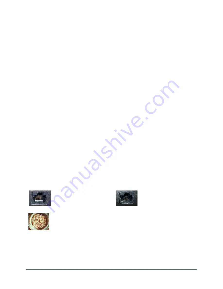
Intact

– will make reliable contact

with cable connector

Damaged

– Bent contact fingers

will NOT make reliable contact
with cable connector

Pro Tip

To prevent tragic mishaps, label both ends of every cable.

6

Installation Guide for the RoboSHOT IW Architectural PTZ Conferencing Camera

Содержание RoboSHOT IW

Страница 1: ...Installation Guide for RoboSHOT IW Architectural PTZ Conferencing Camera Document 411 0016 31 Rev A April 2018 ...

Страница 2: ...ections 8 RoboSHOT IW OneLINK Bridge System 8 RoboSHOT IW OneLINK HDMI System 8 RoboSHOT IW with Third Party Connectivity Solution 9 Installing the Camera Enclosure 10 Before You Start 10 Installing the Camera Enclosure in an Unfinished Wall 10 Installing the Camera Enclosure in a Finished Wall 11 Installing the Camera 12 Installing the Interior Side Panels 12 Installing the Cover 12 Powering Up t...

Страница 3: ...ear Glass Europe UK black primer 999 9966 301 351 What s in this Guide This guide covers n Unpacking the camera n Tips for a successful installation n Information on mounting and connecting the camera n Camera power on Complete product information is available in the Integrator s Complete Guide to the RoboSHOT IW Architectural PTZ Conferencing Camera Download manuals dimensional drawings and other...

Страница 4: ... 150 RoboSHOT IW with Clear Glass Primer Coated North America 999 9966 101 RoboSHOT IW with Clear Glass Black Europe UK 999 9966 151 RoboSHOT IW with Clear Glass Primer Coated Europe UK n Camera n Enclosure assembly black or primed o Rough in box o Interior side plates right and left o Side brackets qty 2 o Drywall clips qty 4 o Screws 6 32 1 4 in qty 12 o Screws 6 32 3 8 in qty 6 o Screws 10 24 1...

Страница 5: ... System with Clear Glass Primer Coated North America 999 9966 201 RoboSHOT IW OneLINK HDMI System with Clear Glass Black Europe UK 999 9966 251 RoboSHOT IW OneLINK HDMI System with Clear Glass Primer Coated Europe UK n Camera n Enclosure assembly black or primed o Rough in box o Interior side plates right and left o Side brackets qty 2 o Drywall clips qty 4 o Screws 6 32 1 4 in qty 12 o Screws 6 3...

Страница 6: ... North America 999 9966 301 RoboSHOT IW OneLINK Bridge System with Clear Glass Black Europe UK 999 9966 351 RoboSHOT IW OneLINK Bridge System with Clear Glass Primer Coated Europe UK n Camera n Enclosure assembly black or primed o Rough in box o Interior side plates right and left o Side brackets qty 2 o Drywall clips qty 4 o Screws 6 32 1 4 in qty 12 o Screws 6 32 3 8 in qty 6 o Screws 10 24 1 in...

Страница 7: ...A sensor in the front of the camera platform receives signals from the remote Make sure there s nothing directly in front of the camera platform and point the remote at the camera Status indicator The multicolored LED indicates the camera s current state n Blue Normal operation blinks off momentarily when the camera receives a command from the remote n Purple In standby mode or booting n Yellow Fi...

Страница 8: ...or damage the product Note that power supplies for different products may look nearly identical always check the label for the output voltage Cabling Notes Use Cat 5e or better cable and standard RJ 45 connectors 568B termination We recommend using high quality connectors and a high quality crimping tool Caution Check Cat 5 cables for continuity before using them Using the wrong pin out may damage...

Страница 9: ... adjacent to the area that the camera enclosure will be set into Cutting or drilling into electrical wiring can cause electrical shock or fire resulting in death injury and damage to the building Warning Before cutting the opening for the camera enclosure ensure that no pipes are present in or immediately adjacent to the area that the camera enclosure will be set into Cutting or drilling into gas ...

Страница 10: ...all the camera verify that it powers up and sends video Referring to the basic connection diagrams connect the camera and verify that video is available on the connected display When you have verified that the camera operates properly disconnect it and continue with the installation Basic Connections Connecting the camera is simple just connect the cable to the OneLINK device or to the Power Data ...

Страница 11: ...RoboSHOT IW with Third Party Connectivity Solution 9 Installation Guide for the RoboSHOT IW Architectural PTZ Conferencing Camera ...

Страница 12: ...nter the enclosure and remove the knock out tab from either the upper or lower face of the enclosure Installing the Camera Enclosure in an Unfinished Wall Follow these steps if the drywall has not yet been installed 1 Measure mark and level the mounting position between two studs 2 Holding the enclosure in place against the wall studs mark the locations for the holes 3 Set the camera enclosure asi...

Страница 13: ...tting or drilling into water or wastewater lines can result in injury and damage to the building 1 Verify that no pipes or wiring pass through or immediately adjacent to the part of the wall where the camera enclosure will be mounted 2 Level measure and mark the cutting lines for the opening 3 Cut the opening 4 Slide the drywall clips into the corners of the enclosure Note Although the drywall cli...

Страница 14: ...o install each interior side panel 1 Insert the tabs into the slots in the back of the enclosure 2 Rotate the interior side panel into place If the enclosure has a smart glass cover ensure that the smart glass cable passes freely through the opening in the right side panel 3 Secure the side panel with 1 4 in 6 32 screws Installing the Cover Do this only after verifying that the camera powers up pr...

Страница 15: ...he camera finishes initializing before trying to operate or control it Next Steps The camera is now ready to configure and use This information is available in the Configuration and Administration Guide for the RoboSHOT IW Architectural PTZ Conferencing Camera It is also included in the Integrator s Complete Guide to the RoboSHOT IW Architectural PTZ Conferencing Camera 13 Installation Guide for t...

Страница 16: ... and or replacement Vaddio Technical Support can be contacted by email at support vaddio com or by phone at one of the phone numbers listed on support vaddio com Return Material Authorization RMA number Before returning a product for repair or replacement request an RMA from Vaddio s technical support Provide the technician with a return phone number e mail address shipping address product serial ...

Страница 17: ...to radio communications Operation of this equipment in a residential area is likely to cause harmful interference in which case the user will be required to correct the interference at his her own expense Operation is subject to the following two conditions 1 This device may not cause interference and 2 This device must accept any interference including interference that may cause undesired operat...

Страница 18: ... Immunity EN 61000 4 4 2004 Corrigendum 2006 Electrical Fast Transients EN 61000 4 5 2006 Surge Immunity EN 61000 4 6 2009 Conducted Immunity EN 61000 4 8 2010 Power Frequency Magnetic Field EN 61000 4 11 2004 Voltage Dips Interrupts and Fluctuations KN24 2008 CISPR 24 1997 A1 2000 A2 2002 IT Immunity Characteristics EN 61000 4 2 Electrostatic Discharge EN 61000 4 3 Radiated Immunity EN 61000 4 4 ...

Страница 19: ... the enclosure 10 11 to a wall stud 10 to drywall 11 O OneLINK 8 P packing lists 2 4 part numbers 2 4 power 8 12 13 on and off 13 options 8 to smart glass cover 12 product capabilities 1 product returns and repairs 14 R requirements installation 7 RJ 45 connector 6 S safety requirements 6 7 site requirements 7 status light meanings of colors 5 structural requirements 7 T typical installation 8 9 V...

Страница 20: ...dio RoboSHOT and OneLINK are trademarks or registered trademarks of Milestone AV Technologies HDBaseT and the HDBaseT Alliance logo are trademarks of the HDBaseT Alliance Exmor is a trademark of Sony Corporation All other brand names or marks are used for identification purposes and are trademarks of their respective owners In British Columbia Milestone AV Technologies ULC carries on business as M...

Отзывы: