Quick-Connect CCU Kit for BRC-H900 Camera
© 2012 Vaddio - All Rights Reserved. Document Number 342-0507 Rev A Page 10 of 16
Step 3:
Take the Wall Mount, with the EZIM CCU and break out cable installed, and place it against the drywall anchors
or 3-gang wall box, making sure to pull the three Cat-5 cables through the oval pass-through hole. Finger-tighten
the screws to the mount and confirm that the base is level. Tighten the screws firmly. If the bracket is to be
mounted on a 3-gang wall box, use the screws supplied with the electrical box.
Step 4:
Confirm that the Cat. 5 cables are terminated correctly, by testing them with a continuity tester. Connect the
break out cables to the appropriate ports on the BRC-H900 (8-pin Mini DIN is connected to VISCA IN). Push the
camera into place and dress the cables. Secure the camera to the mount and using the ¼”-20 screws.
Step 5:
The Quick-Connect CCU is a 1-RU rack mount interface that breaks out the signals from the Cat. 5 cables back
to the standard connectors. Connect the other side of the appropriate Cat-5 cable to the CCU except for power.
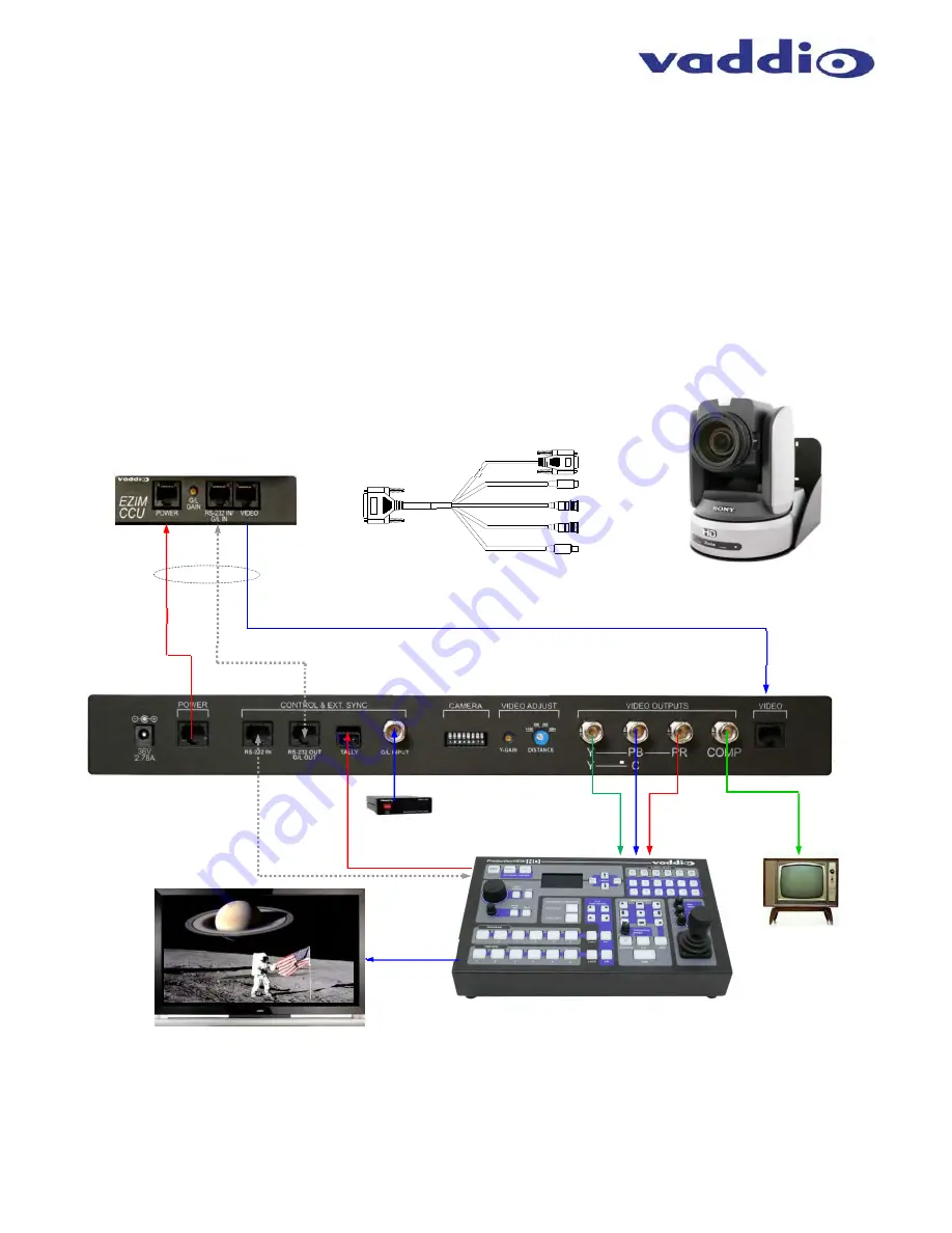
The basic system connectivity is illustrated below.
Drawing: Basic System Connectivity
Wiring Diagram Example:
System Configuration Notes:
The Quick-Connect CCU System uses a Cat-5 (all 4-pairs) for power to ensure the motors receive the required current to operate properly.
The Video Cat-5 cable uses all four pairs for video. The RS-232 Cat-5 provides communication to the camera for CCU and PTZ control and
G/L (where applicable) to the camera. These Cat. 5 cables can be run up to 500’ (152.4m). See Appendix 1 for wiring and pin-out
information.
NOTE
: Daisy-Chain configurations are not supported.
Cat-5 Cables
up to 500’
HD Break-out
Cable
EZIM CCU Top Panel
Power
RS-232 & G/L
HSDS Video on Cat-5
RS-232
Tally
ProductionVIEW HD
HD-YPbPr Out
RS-232
CVBS
G/L
POWER
Quick-Connect CCU
BRC-H900 Camera, Wall Mount
with EZIM CCU (behind camera)
Note: Camera not included
HD YPbPr
+
G
Composite
Video
Simulated Video Feed
HD Video
G/L Box


