background image

Cleaning and maintenance

68

20901334_EN-US_PC3000 VARIO select Serie_V1.4_061022

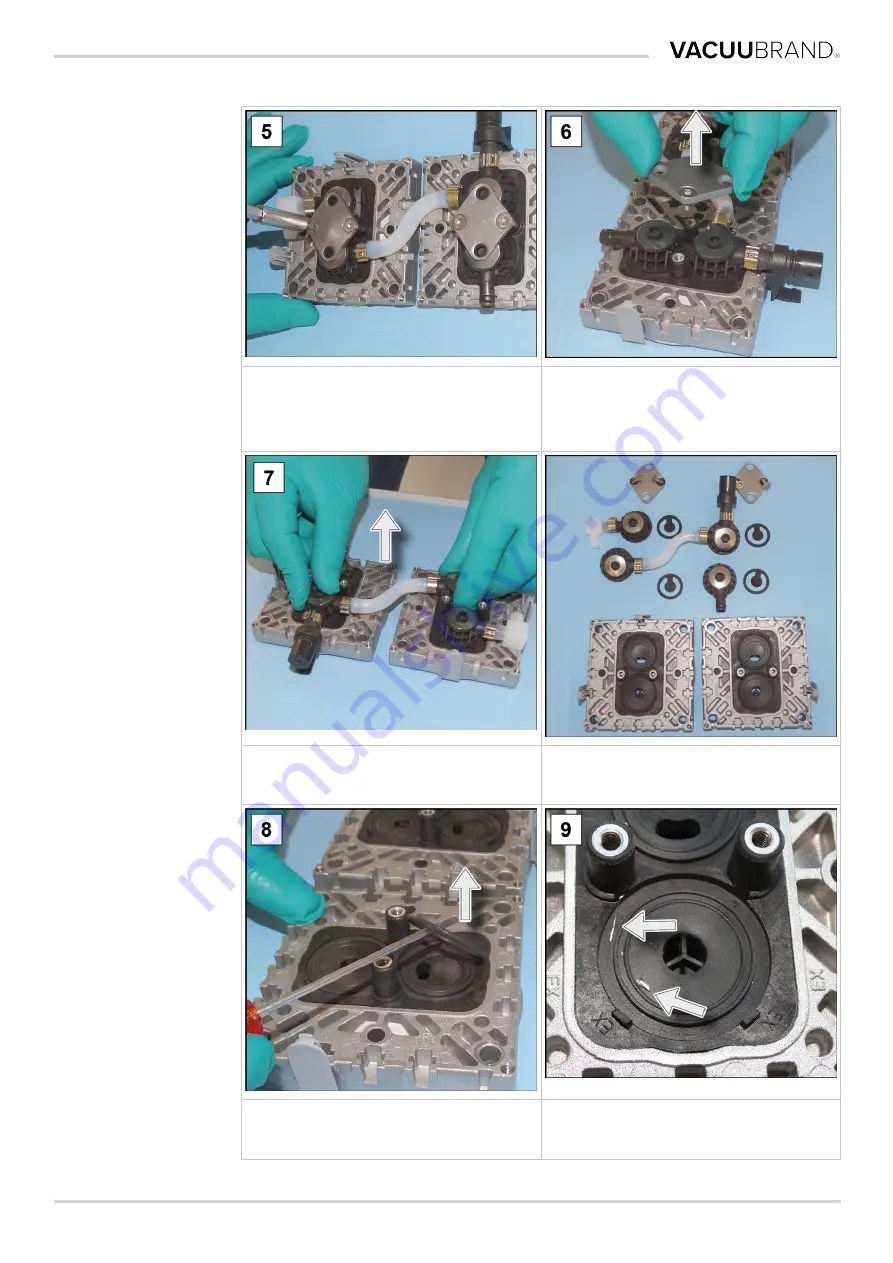
5. Undo the Torx screws on the

clamping brackets; Torx
screwdriver TX20.

6. Remove the clamping

brackets from the valve
clusters.

7. Remove the valve clusters

with the cup springs.

Top view: Components valve clusters,
valves and pump head pair.

8. Carefully remove the used

O-rings and valves.

9. Check the surfaces for soil-

ing.

Содержание PC 3002 VARIO select

Страница 1: ...Chemistry pumping unit series PC 3002 VARIO select PC 3003 VARIO select PC 3004 VARIO select PC 3004 VARIO select EKP Instructions for use Original instructions EN US 20901334 ...

Страница 2: ...e product Thank you for purchasing this product from VACUUBRAND GMBH CO KG You have chosen a state of the art high quality prod uct Manufacturer VACUUBRAND GMBH CO KG Alfred Zippe Str 4 97877 Wertheim GERMANY Head office 49 9342 808 0 Sales 49 9342 808 5550 Service 49 9342 808 5660 Fax 49 9342 808 5555 E mail info vacuubrand com Web www vacuubrand com Imprint 2 20901334_EN US_PC3000 VARIO select S...

Страница 3: ...rget group description 15 2 4 General safety information 16 2 5 Protective clothing 16 2 6 Safety measures 16 2 7 Laboratory and work materials 17 2 8 Possible sources of danger 19 2 9 Motor protection 21 2 10 ATEX device category 21 2 11 Disposal 23 3 Product description 24 3 1 Basic configuration of pumping unit series 24 3 2 Chemistry pumping unit series 25 3 3 Condensers and coolers 26 3 3 1 S...

Страница 4: ...oubleshooting 50 6 1 Technical assistance 50 6 2 Error cause corrective measure 50 7 Cleaning and maintenance 54 7 1 Information on service activities 55 7 2 Cleaning 57 7 2 1 Housing surface 57 7 2 2 Emptying the glass flask 58 7 2 3 Cleaning or replacing PTFE molded hoses 58 7 3 Vacuum pump maintenance 59 7 3 1 Maintenance items 59 7 3 2 Changing the membranes and valves 61 7 3 3 Replacing a dev...

Страница 5: ...w the safety instructions n In addition to the information in this User manual please also observe the applicable national regulations on accident preven tion and occupational safety General General information n When passing this product on to third parties please also in clude the User manual n All figures and drawings are examples and are solely intended for the purpose of better understanding ...

Страница 6: ...rvice department please have the serial number and product type on hand see the nameplate on the product 1 2 Instruction manual layout Manual organization The instruction manual for the pumping unit the controller and available accessories is organized in a modular format this means that the instructions are divided into individual separate instruction brochures Instruction modules Pumping unit se...

Страница 7: ...otentially dangerous situation Failure to observe this warning may result in danger to life or serious injury Ø Please follow the instructions for prevention CAUTION Indicates a potentially dangerous situation Failure to observe this caution may result in minor injuries or material damage Ø Please follow the instructions for prevention NOTICE Reference to a potentially harmful situation Failure to...

Страница 8: ...anger sign Warning of electrical voltage Warning of hot surface Electrostatically sensitive components ESD General mandatory action sign Disconnect power plug from electrical outlet Other symbols and pictograms Additional symbols Positive example Right Result o k Negative example Wrong Reference to content in this User manual Reference to content in sup plementary documents Ensure sufficient air c...

Страница 9: ...f the action Action instructions multiple steps 1 First action step 2 Next action step R Result of the action Action instructions that require several steps must be followed in the order they are described Action instructions image description Example Principle presenta tion Operating steps presented in images 1 First action step 2 Next action step R Interim result or result of the action ...

Страница 10: ...ubber Gas type ind Gas type independent GB Gas ballast If necessary If necessary Size Size IK Immission condenser IN1 Inlet vacuum connection KF Small flange Max Maximum value Min Minimum value w o EK Without emission condenser PA Polyamide PBT Polybutylene terephthalate PC Chemistry pumping unit with type code PE Polyethylene RMA No Return authorization number so called so called SW Wrench size t...

Страница 11: ... external cooling medium Dry ice condenser 2 Cooling condenser with receiving flask and dry ice as cooling medium installed at the outlet pressure side VACUU BUS VACUUBRAND bus system for the communication of pe ripheral devices with VACUU BUS capable measuring equipment and controllers VACUU BUS ad dress Address that enables a clear assignment of the VACUU BUS client in the bus system e g for the...

Страница 12: ...s purpose Attached coolers emission condenser immission condenser dry ice cooler Peltronic emission condenser including separator and flask are exclusively designed for condensing vapors Application example Evacuating distillation instruments rotary evaporation facilities with VACUU LAN network vacuum drying The vacuum system should only be used in a dry non explosive en vironment Proper use also ...

Страница 13: ...pumping and condensing solid materials or liquids 2 1 3 Foreseeable misuse Misuse In addition to improper use there are other types of use that are for bidden when handling the device Forbidden types of use are primarily n use on people or animals n setup and operation in a potentially explosive environment n use in mining or underground n using the product to generate pressure n fully exposing va...

Страница 14: ...heg Target group descrip tion on page 15 must have the corresponding qualification for the listed activities Only qualified electricians are permitted to carry out special work on electrical equipment Personnel responsibilities Personnel responsi bilities For activities that require protective clothing the personal protec tion equipment specified by the operator must be worn When the vacuum system...

Страница 15: ...t The assigned work can be assessed and potential dangers detected Responsible spe cialist Qualified employee with additional field department or division responsibility who is assigned by the operator Responsibility matrix Who does what ma trix Task Operator Qualified em ployee Responsible spe cialist Installation x x x Initial operation x x x Network integration x Operation x x x Fault reporting...

Страница 16: ...ls 2 6 Safety measures Manufacturer mea sures Products of VACUUBRAND GMBH CO KG are subject to high qual ity control requirements in terms of safety and operation Each product is put through an extensive test program before delivery Operator measures Operator measures ð Use your vacuum only when you have understood the instruc tion manual and the operation ð Replace defective components immediatel...

Страница 17: ...ow can damage the vacuum pump Hazardous substances can form de posits in the vacuum pump Possible protective measures Protective measures depending on the ap plication ð Rinse the vacuum pump with inert gas or air before you change the pumping medium ð Use inert gas to dilute critical mixtures ð Prevent the release of hazardous toxic explosive corrosive health damaging or environmentally harmful f...

Страница 18: ...pump design Particles liquids and dust are not permitted inside the vacuum pump ð Do not pump any substances that can form deposits inside the vacuum pump ð Install suitable separators and or filters in front of the inlet Suitable filters are chemical resistant clog free and ensure a constant flow rate ð Replace porous vacuum hoses promptly ...

Страница 19: ...ifferential pressure between inlet and outlet in accordance with the technical data ð The system to be evacuated and all hose connections must be mechanically stable ð Attach the coolant hoses to the hose nozzles so that they do not come loose unintentionally Preventing condensate return flow Preventing backlog in the exhaust line Condensate can damage the pump head Condensate must never flow back...

Страница 20: ... Surface tempera tures The surface of vacuum pumps can reach temperatures greater than 70 C during operation especially when vacuuming heated media ð Avoid direct contact with the surface or wear heat resistant safety gloves if contact cannot be excluded ð Provide contact protection if the surface temperature should be elevated on a regular basis ð Allow the vacuum pump to cool down before perform...

Страница 21: ...otor is blocked the vacuum pump switches off Restart procedure If the vacuum pump switches off due to these safety measures the fault must be reset manually Disconnect the pumping unit from the power supply Eliminate the cause of the error Restart the pumping unit 2 10 ATEX device category Installation and explosive environment Installation and operation in areas where an explosive atmos phere can...

Страница 22: ... that in all probability explosive mixtures are only briefly or rarely produced ð If necessary ventilate with inert gas Information about the ATEX device category can be found online ATEX information Restrictions on operating conditions Explanation of usage conditions X Type plate example Meaning for devices marked with X n The devices have a low mechanical protection and must be in stalled so tha...

Страница 23: ...nvironment or human health Discarded electronic equip ment also contains valuable raw materials which can be recov ered if properly disposed of for recycling End users are required by law to bring waste electrical and elec tronic equipment to an approved collection site ð Please properly dispose of electrical waste and electronic com ponents at the end of their service life ð Observe the national ...

Страница 24: ...ic configuration of pumping unit series View and basic con figuration PC 300x VARIO select Meaning 1 Power connection device fuse interfaces VACUU BUS Ethernet RS232 2 On Off switch rocker switch pumping unit 3 Emission condenser EK 4 Outlet Exhaust connection 5 On Off button VACUU SELECT Controller 6 VACUU SELECT Sensor installed in pumping unit housing 7 Chemical membrane pump 8 Gas ballast valv...

Страница 25: ...try pumping unit Pump head Steps AK EK EKP a PC 3002 VARIO select 2 2 b PC 3003 VARIO select 4 4 c PC 3004 VARIO select 4 3 d PC 3004 VARIO select EKP 4 3 Product specific abbreviations Product specific ab breviations AK Separator flask installed at inlet or outlet EK Emission condenser installed at outlet EKP Peltronic emission condenser installed at outlet PC Chemistry pumping unit with type cod...

Страница 26: ... 1 Separator condenser at inlet Connection on separator flask Connections on AK Meaning 1 Vacuum inlet connection IN 3 3 2 Condenser at outlet Connection and coolant on emission condenser Connections on EK Meaning 1 Outlet connection coolant EX 2 Inlet connection coolant IN e g water 3 Outlet connection EX ...

Страница 27: ...s on the Peltronic emission condenser Connections on EKP 1 Outlet connection EX 2 Vacuum pump connection 3 VACUU BUS connection 4 Power connection with on off switch ð For detailed information and descriptions about the Peltronic emission condenser see the Peltronic EK instruction manual ...

Страница 28: ...l area vacuum network Example Local area vacuum network Description 1 Process example VACUU LAN local area vacuum network with three valve modules 2 Vacuum hose permanently installed PTFE hose lines 3 Lab furniture 4 Exhaust gas hose diverted into a fume hood 5 PC 3004 VARIO select EKP vacuum pumping unit ...

Страница 29: ..._PC3000 VARIO select Serie_V1 4_061022 29 Drying Example Drying Description 1 Chiller 2 Coolant hoses 3 Exhaust gas hose diverted into a fume hood 4 PC 3002 VARIO select vacuum pumping unit 5 Vacuum hose 6 Process example drying cabinet ...

Страница 30: ...ð If possible keep the original packaging e g for sending in for re pairs Incoming goods ð Check the delivery immediately after receipt for any transport damage and for completeness ð Promptly report transport damage to the supplier in writing Unpacking Example Pumping unit in orig inal packaging Glass flask in en closed box 1 Remove the connections from the glass flask such as hose noz zles and s...

Страница 31: ...t the pumping unit can weigh more than 20 kg Lift the device out of the packaging using the recessed grips on the sides Never use attachment parts such as brackets or glass flasks to aid in lifting Use only the recessed grips on the sides and or the handle to transport it to the installation location ...

Страница 32: ...itions Calibrating the in stallation conditions n The device is acclimatized n The ambient conditions are met and lie within the limitations of use n The pump must installed on a stable and secure floor with no other mechanical contact apart from the pump feet Installing the vacuum pump Example Sketch of minimum distances in labora tory furniture ð Place the vacuum pump on a stable vibration free ...

Страница 33: ... take note of the specifica tions from the type plate and in the chapter technical data 4 3 Connection supply connections On the pumping unit supply connections are provided for vacuum and exhaust and optionally for gas ballast ventilation and coolant Set up the connection for your pumping unit as described in the fol lowing examples Also attach the provided screw fasteners and glass flasks to the...

Страница 34: ...t inlet IN 1 Join the sealing ring a the cap nut b and hose nozzle c as pictured 2 Slide the vacuum hose d from the apparatus onto the hose nozzle and fasten the vacuum hose e g with a hose clamp You will achieve the optimal vacuum for your application if you ob serve the following points ð Connect the shortest possible vacuum line with the maximum possible cross section ð Use a vacuum hose with s...

Страница 35: ...of pressure Ø Always lay the exhaust hose so that it is descending or take measures to prevent condensate return flow into the vacuum pump Ø Observe the maximum allowable pressures and pressure differentials Connecting the exhaust hose Example Exhaust connection at outlet EX 1 Join the rubber sealing ring a the hose nozzle b and the cap nut c as pictured and screw this onto the connection 2 Slide ...

Страница 36: ...suitable for cooling n In a closed internal coolant circuit the pressure should be lim ited to 3 bar 44 psi n A cooling water valve may only be installed in the inflow the coolant outflow must be open and free of pressure Connecting coolant Example Coolant connection on EK 1 Fasten both hose nozzles a with the union nut b to the con denser as pictured 2 Attach the hoses for the coolant according t...

Страница 37: ...tion or other dangerous situations can occur Ø Never ventilate processes with air in which a potentially explosive mixture can form Ø When flammable substances are present use only inert gas for ventilation e g nitrogen max 1 2 bar 900 Torr abs Vent with ambient air5 Position of venting connection Nothing must be connected to venting valve a for venting with am bient air 5 Only applicable to senso...

Страница 38: ...s connect venting valve6 Required connection material Hose for inert gas connection Ø 4 mm e g silicone tube 4 6 mm Venting valve inert gas connection 1 Insert hose b into VENT connection a and secure the hose with the union nut 2 Connect hose b to inert gas max 1 2 bar 900 Torr abs 6 Avoid overpressure ...

Страница 39: ...ocess a potentially explosive mixture can form due to oxygen in the air or other dangerous situations can occur Ø In the presence of flammable substances and for pro cesses in which a potentially explosive mixture can oc cur use only inert gas as a gas ballast e g nitrogen max 1 2 bar 900 Torr abs Gas ballast valve po sition If ambient air is to be used as gas ballast nothing needs to be con necte...

Страница 40: ...nnection options and adapters for hose nozzles or small flanges 4 4 Electrical connection Connecting the pumping unit to the electrical system Example Electrical connection of the pumping unit 1 Plug the socket a of the power cable into the power connec tion of the vacuum pump 2 Connect the power plug b to the power outlet R Pumping unit connected to the electrical system NOTICE Lay the power cabl...

Страница 41: ...g that matches your power connection ð Do not use multiple socket power strips as a power connection ð The power plug also works as a circuit breaker Set up the de vice so that the plug can be easily disconnected from it Connection options for vacuum accessories The VACUU BUS interface functions as the power supply and control line for vacuum accessories 1 Connect your accessories to your controll...

Страница 42: ...Installation and connection 42 20901334_EN US_PC3000 VARIO select Serie_V1 4_061022 Example Schematic drawing of controller with connected valve and sensors Accessories see chapter Ordering information ...

Страница 43: ...mechanics of a PC 300x VARIO select series pumping unit The operation of an installed vacuum regulator 7 and its functions are described in the instruction manual of a VACUU SELECT 5 1 Switching on Switching on the pumping unit Switching on 1 Switch on the rocker switch a switch position I 2 Press the ON OFF button b on the controller R Display with start screen R After approx 30 seconds the proce...

Страница 44: ...erator interface VACUU SELECT with process display Process display Pressure display for a process 1 Status bar 2 Analog pressure display pressure curve 3 Digital pressure display pressure value target value actual value pres sure unit 4 Process display with context functions 5 Screen navigation 6 Controls for the controller ...

Страница 45: ...Stop Stop an application always possible VENT8 Ventilate system Option Button press 2 Sec briefly ventilate regulation continues Button press 2 Sec ventilate to atmospheric pres sure vacuum pump is stopped Button press during ventilation ventilation is stopped Favorites Call up Favorites menu 8 The VENT button is only shown if a ventilation valve is connected or activated ...

Страница 46: ...Operation 46 20901334_EN US_PC3000 VARIO select Serie_V1 4_061022 5 2 2 Operation Starting the vacuum controller Start Stopping the vacuum controller Stop Ventilating Ventilating ...

Страница 47: ... Operating the gas ballast valve ð Turn the black gas ballast cap in any direction to open or close the gas ballast valve ð If possible only evacuate the condensable vapors e g water vapor solvents etc when the vacuum pump is at operating temperature and the gas ballast valve is open ð Connect inert gas as the gas ballast to prevent and exclude the formation of potentially explosive mixtures durin...

Страница 48: ...continue run ning for approx 30 minutes with open gas ballast or open inlet IN R Condensate and residual media are rinsed out of the vac uum pump NOTICE Avoid deposits and rinse the condensate out of the pump 2 Switch off the rocker switch a switch position 0 R Pumping unit switched off 3 Disconnect the power plug 4 Disconnect the pumping unit from the equipment 5 Empty the glass flasks 6 Check th...

Страница 49: ...he pumping unit into storage Especially if it has been in operation for more than 15 000 hours 3 Seal off the suction and exhaust line e g with the transport caps 4 Pack up The pumping unit so that it is protected from dust pos sibly include a drying agent 5 Store The pumping unit in a cool and dry location NOTICE If for operational reasons damaged parts are stored these should be clearly marked a...

Страница 50: ...te from the refer ence standard Sensor dirty Humidity in sensor Sensor defective Sensor not measur ing correctly Clean sensor mea suring chamber Allow sensor measur ing chamber to dry e g by draining Calibrate sensor with reference measuring device Replace defective components Qualified employee Sensor does not transmit measure ment No voltage applied VACUU BUS plug connection or cable defective o...

Страница 51: ... Ensure that nothing is blocking the line Operator Vacuum pump stopped Vacuum pump does not start Motor overloaded Motor overheating Thermal protection activated Check coolant con nection Ensure coolant sup ply Allow the motor to cool down Manually reset fault Disconnect the pumping unit from the power Eliminate the error cause Restart the pump ing unit Qualified employee No suction capacity or ve...

Страница 52: ... serted Controller switched off or defective Switch on Pumping unit Check the power connection and ca ble Check the VACUU BUS plug connection and cable to the con troller Replace defective components Operator Condenser cooler defective Mechanically dam aged Send in Resp spe cialist Loud operating noises No hose installed Check hose and in stall correctly Operator Loud operating noises Exhaust line...

Страница 53: ...N US_PC3000 VARIO select Serie_V1 4_061022 53 Error Cause Corrective measure Personnel Default setting of the speed on the con troller too low e g draining with speed 5 Controller regulates the motor with a speed that is too low ...

Страница 54: ...al protective equipment e g safety gloves eye protection and if required a respirator ð Decontaminate the vacuum pump before you open it If required have the vacuum pump decontaminated by an external service provider ð Take safety precautions when handling hazardous ma terials in accordance with your operating instructions NOTICE Carrying out work in an improper manner may cause dam age ð Have Mai...

Страница 55: ...d hose x Replace pressure release valve on EC x Clean pumping unit x Recommended auxiliary equipment Example Recom mended auxiliary equipment for clean ing and maintenance Meaning No Auxiliary equipment 1 Mat for round flasks 2 Protective gloves 3 Chemical resistant container and funnel 9 Recommended maintenance interval according to hours of operation and under normal oper ating conditions depend...

Страница 56: ...ench 20636554 SW66 3 Flat nose pliers Closing hose clamps 4 Flat head screwdriver Opening hose clamps Size 1 5 Hexagon socket wrench Screw fasteners for head cover Screw fasteners for EKP bracket Size 5 Size 4 6 Torx screwdriver Screw fasteners for EK counterholder Screw fasteners for housing cover Fastening loosening clamping brackets Screw fastener for gas ballast TX10 TX20 TX20 TX20 7 Torque wr...

Страница 57: ...ed components such as glass flasks The temperatures that are produced during operation may cause burns Ø Use protection against accidental contact especially when the exhaust temperature is persistently high Ø Allow the instrument to cool before you empty the glass flask or begin performing maintenance tasks Ø For tasks that must be performed during operation use your personal protection equipment...

Страница 58: ...r e g a chemical resistant canister 3 Reattach the glass flask separator to the condenser with the joint clamp Depending on the application the collected liquid can either be re cycled or properly disposed of 7 2 3 Cleaning or replacing PTFE molded hoses Maintenance provides an opportunity to check the components of the pumping unit including the hosing ð Clean the inside of highly soiled molded h...

Страница 59: ...e items 1 Pump heads power connection side 2 Pump heads EK side ð Carry out maintenance on pump heads in succession ð Always completely change membranes and valves on the pump heads as described in the illustration for pump head 1A Simple maintenance due to divided work steps ð First replace the membranes on one pump head pair ð Change the inlet outlet valves next ð Then perform these tasks on the...

Страница 60: ...ample Exploded view draw ing of pump head Meaning Valve maintenance 1 Head cover screw fasteners 2 Clamping bracket screw fasteners 3 Cup springs 4 Valve clusters 5 Valves 6 O rings size 26 x 2 Membrane maintenance 7 Head cover screw fasteners 8 Membrane spring washer with square head screw 9 Membrane 10 Membrane support disc ...

Страница 61: ...ging the membranes and valves Preparation Example Preparing for mainte nance 1 Switch off the pumping unit and disconnect the power plug 2 Remove the glass flask and connected hoses Example Disassembling the EK optional 3 Undo the screws from the counterholder Torx screw driver TX10 4 Remove the counterholder and set it aside together with the screws ...

Страница 62: ...VARIO select Serie_V1 4_061022 5 Unscrew the cap nut pull off the molded hose and re move the cooler 6 Put the cooler down safely so that no liquid can leak out n Here you can check the pressure release valve of the EK and re place it in case of damage ...

Страница 63: ...mantling device and housing parts Example Dismantling housing parts left side 1 Undo the screw fasteners from the head cover Torx screwdriver TX20 2 Remove the head cover and set it aside 3 Open the hose clamps of the outer hoses Flat head screwdriver size 1 4 Pull the molded hoses off ...

Страница 64: ...ad pair Replacing membranes Example Membrane replace ment 1 Gently press against one of the membrane spring wash ers 2 Fold the membrane forward on the sides 3 Carefully position the mem brane wrench onto the membrane support disc and unscrew the assembly with the membrane wrench fixed in place 4 Lift the membrane with all its parts out of the vacuum pump If spacers are stuck to the connecting rod...

Страница 65: ...g rod n Keep the spacers for later use It is imperative that these are re installed in the same quantity 5 Pull the membrane spring washer out and remove the used membrane 6 Place the new membrane onto the square bolt of the membrane spring washer n Make sure that you install the membrane correctly with the coated light side on top n Ensure that it is correctly po sitioned on the square bolt ...

Страница 66: ...61022 7 Place all spacers onto the threaded bolt 8 Attach the membrane as sembly in the membrane wrench 9 Hold onto the spacers and carefully place all compo nents into the threaded hole of the connecting rod 10 Tighten the assembly by hand at first using the mem brane wrench ...

Страница 67: ...nch and tighten the assembly to 6 Nm 12 Repeat the steps for chang ing the second membrane Replacing valves Example Valve change Fig 2 4 optional de scription only ap plies to pump head with gas ballast GB 1 Take the pump head pair that was set aside 2 Pull off the gas ballast cap 3 Carefully pry open the cover 4 Undo the screw fastener Torx screwdriver TX20 ...

Страница 68: ...screws on the clamping brackets Torx screwdriver TX20 6 Remove the clamping brackets from the valve clusters 7 Remove the valve clusters with the cup springs Top view Components valve clusters valves and pump head pair 8 Carefully remove the used O rings and valves 9 Check the surfaces for soil ing ...

Страница 69: ...ert new sealing rings into the notches 12 Apply the new valves and align them Top view detail Correct positioning of the valves IN Inlet Inlet EX Exhaust Outlet 13 Place both valve clusters with the cup springs onto the pump heads 14 Place the clamping brackets on the valve clusters and tighten the screw fasteners by hand ...

Страница 70: ...n the screw fasteners by hand Assembling device and housing parts Before you put the pumping unit back into operation all device and housing parts that were removed must first be re attached Example Assembling device and housing parts 1 Carefully press the mem branes centrally and flush into the housing opening 2 Hold the pump head pair on the vacuum pump and tighten the screw fasteners hexagon so...

Страница 71: ...he screw fasteners crosswise to 12 Nm with a torque wrench 4 Slide the molded hoses back onto the connections 5 Close the hose clamps on the hose nozzles e g with flat nose pliers 6 Put on the head cover so that it fits Fig 8 optional de scription only ap plies to pump head with gas ballast GB ...

Страница 72: ...the previous description for changing the membrane and valve If the maintenance work is fully completed ð Connect the hosing for operation ð Connect the pumping unit to the power supply R Pumping unit ready for restart R Without reconnection Pumping unit prepared for stor age 7 3 3 Replacing a device fuse At the power connection on the back side of the pumping unit there are 2 device fuses type 6 ...

Страница 73: ...Cleaning and maintenance 20901334_EN US_PC3000 VARIO select Serie_V1 4_061022 73 3 Replace defective fuses 4 Slide the fuse holder back onto the fuse socket ...

Страница 74: ...9 IP 20 Protection class UL 50E Type 1 Avoid condensate or contamination from dust liquids and corrosive gases Operating conditions US Operating temperature 10 40 C 50 104 F Storage transport temperature 10 60 C 14 140 F Maximum permissible media temperature gas of non explosive atmospheres short term 80 C 176 F Continuous operation 40 C 113 F ATEX conformity II 3 G Ex h IIC T3 Gc X Internal Atm O...

Страница 75: ...rpm Overvoltage category II Interface VACUU BUS Power cable 2 m Device fuse 2x 6 3 A t 5x20 8 A t 5x20 Vacuum data US Inlet pressure outlet pres sure differential pressure ab solute 1 1 bar 825 Torr Pressure at gas connections absolute max 1 2 bar 900 Torr Sensor integrated integrated Measurement principle Ceramic membrane aluminum oxide capac itive gas type independent absolute pres sure Measurem...

Страница 76: ...ders steps 4 3 Weights and dimensions L x W x H US PC 3002 VARIO select 419 mm x 243 mm x 444 mm 16 5 in x 9 57 in x 17 48 in Weight 17 9 kg 39 5 lb PC 3003 VARIO select 419 mm x 270 mm x 457 mm 16 5 in x 10 63 in x 18 in Weight 21 1 kg 46 6 lb PC 3004 VARIO select 419 mm x 268 mm x 457 mm 16 5 in x 10 55 in x 18 in Weight 21 1 kg 46 6 lb PC 3004 VARIO select EKP 402 mm x 361 mm x 457 mm 15 83 in ...

Страница 77: ...orced PP blind plate Outlet PET Distributor head PPS fiberglass reinforced O ring on separator Fluoroelastomer Pressure release valve on emission condenser Silicone rubber PTFE film Emission condenser Borosilicate glass Round flask Borosilicate glass Separator PMP Tubing PTFE Hose screw connection ETFE ECTFE O ring on separator Fluoroelastomer NBR Peltronic emission condenser ETFE ECTFE PP PA Soun...

Страница 78: ...rom the type plate This way we can provide you with targeted support and consultation for your product Pumping unit type plate general Example Type plate details Ultimate vacuum ATEX specification Manufacturer Year of manufacture month Suction capacity Serial number Supply voltage Product series model Option Approval marking symbols Protection class Specification of the documentation group and cat...

Страница 79: ...nsor 20612881 VSK 3000 20640530 DAkkS calibration with first delivery 20900214 DAkkS recalibration 20900215 Order data replace ment parts Replacement parts Order No Hose nozzle 6 curved 20639948 Hose nozzle DN 6 10 20636635 Small flange KF DN 16 20635008 Extension cable VACUU BUS 0 5 m 20612875 Extension cable VACUU BUS 2 m 20612552 Extension cable VACUU BUS 10 m 22618493 Spherical joint clamp VA ...

Страница 80: ...its Supply sources International agents and dealers Purchase original accessories and original replacement parts from a branch office of VACUUBRAND GMBH CO KG or from your local dealer ð Information about the complete range of products can be found in the current product catalog ð Your local dealer or VACUUBRAND sales office is available for or ders questions about vacuum regulation and the ideal ...

Страница 81: ...r process n On site service on request n Calibration DAkkS accreditation n With clearance certificate Returns disposal Additional information can be found on our website www vacuubrand com Service procedure Follow the description at VACUUBRAND Support Service Reduce downtimes speed up processing When contacting our service department please have the required information and documents ready ð Your ...

Страница 82: ...Annex 82 20901334_EN US_PC3000 VARIO select Serie_V1 4_061022 8 6 EU declaration of conformity ...

Страница 83: ...Annex 20901334_EN US_PC3000 VARIO select Serie_V1 4_061022 83 8 7 UKCA conformity declaration ...

Страница 84: ...I Improper use 13 Installing the vacuum pump 32 Instruction modules 6 L Labels and signs 21 Looking out for dangers during venti lation 20 M Maintenance interval 55 Maintenance of pump heads 59 Measuring chamber 77 Membrane replacement 64 Misuse 13 Modular instruction manuals 6 O Observe stability 19 Operator interface 44 Operator responsibilities 14 Operator safety measures 16 Overheating protect...

Страница 85: ...placing membranes 64 Restart procedure 21 Rough vacuum 11 S Safety instructions 12 Separator flask 25 Separator flask connections 26 Surface temperatures 20 Switching on 43 Switching on the pumping unit 43 T Target groups 15 Technical data 74 V Vacuum connection at inlet 34 Valve replacement 67 Vent inert gas 38 Vent with ambient air 37 W Warning messages 7 Wetted materials 77 Who does what matrix...

Страница 86: ...86 20901334_EN US_PC3000 VARIO select Serie_V1 4_061022 ...

Страница 87: ...20901334_EN US_PC3000 VARIO select Serie_V1 4_061022 87 ...

Страница 88: ...RMANY Head office 49 9342 808 0 Sales 49 9342 808 5550 Service 49 9342 808 5660 Fax 49 9342 808 5555 E mail info vacuubrand com Web www vacuubrand com Version 20901334_EN US_PC3000 VARIO select Serie_V1 4_061022 Steffl VACUUBRAND GMBH CO KG 2022 VACUUBRAND Support Manuals ...

Отзывы: