


39
20901544_E12C+16C_NT Vsel_V1.2_260922
Commissioning (operation)
5
5 Commissioning (operation)
Commissioning (operation)
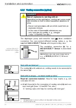
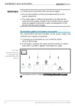
Before putting into operation, make sure that the activities de
‑
scribed in the chapter Installation and power connection have
been carried out properly.
5.1
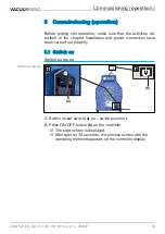
5.1 Switch on
Switch on
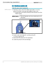
Switch pump on
(b)
1
(a)
2
1.
Switch rocker switch
(a)
on – switch position
I
.
2.
Press ON/OFF button
(b)
on the controller.
5
The start screen is displayed.
5
After approx. 30 seconds, the process screen with the
operating elements appears on the controller display.
Switch pump on
Содержание MD 12C NT VARIO o.C.
Страница 26: ...26 20901544_EN_Mx10C 12C 16C_NT Vsel_V1 2_260922 Product description...
Страница 46: ...46 20901544_EN_Mx10C 12C 16C_NT Vsel_V1 2_260922 Commissioning operation...
Страница 90: ...90 20901544_EN_Mx10C 12C 16C_NT Vsel_V1 2_260922...
Страница 91: ...91 20901544_EN_Mx10C 12C 16C_NT Vsel_V1 2_260922...


