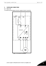


cabling and connections
vacon • 41
24-hour support: +358 (0)201 212 575 • Email: [email protected]
6
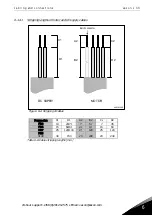
NXOPTA2
21
RO1/1
Relay output 1
Switching capacity
24VDC/8A
250VAC/8A
125VDC/0.4A
Min.switching load
5V/10mA
22
RO1/2
23
RO1/3
24
RO2/1
Relay output 2
Switching capacity
24VDC/8A
250VAC/8A
125VDC/0.4A
Min.switching load
5V/10mA
25
RO2/2
26
RO2/3
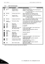
Table 6
-
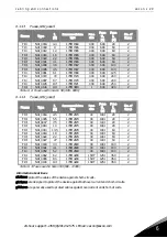
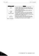
10. Control I/O terminal signals on basic relay board NXOPTA2
NXOPTA3
21
RO1/1
Relay output 1
Switching capacity
24VDC/8A
250VAC/8A
125VDC/0.4A
Min.switching load
5V/10mA
22
RO1/2
23
RO1/3
25
RO2/1
Relay output 2
Switching capacity
24VDC/8A
250VAC/8A
125VDC/0.4A
Min.switching load
5V/10mA
26
RO2/2
28
TI1+
Thermistor input
29
TI1–
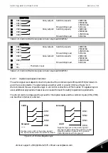
Table 6
-
11. Control I/O terminal signals on basic relay board NXOPTA3
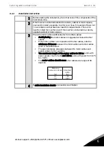
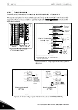
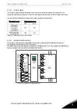
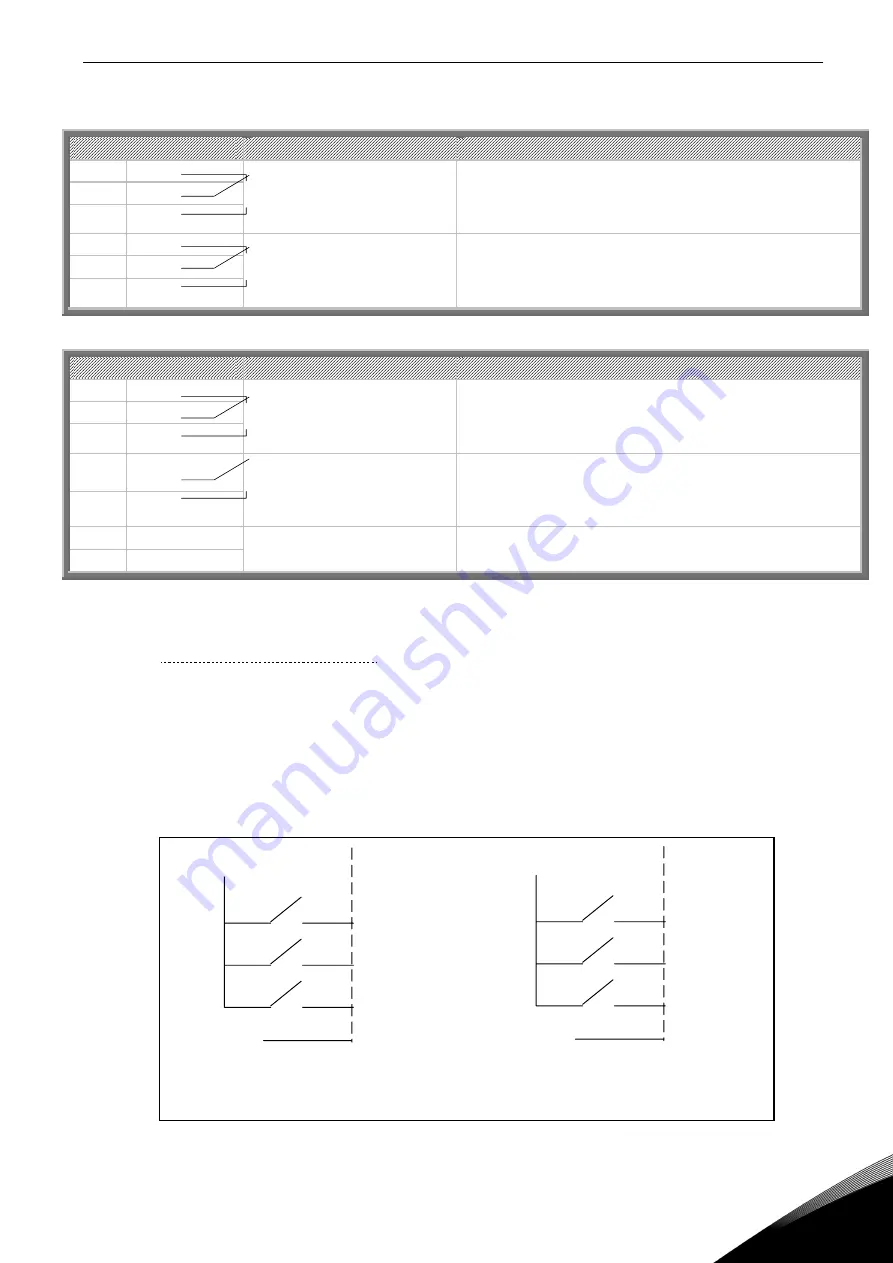
6.2.2.1
Digital input signal inversions
The active signal level depends on which potential the common inputs CMA and CMB (terminals 11
and 17) are connected to. The alternatives are 24V or ground (0 V). See Figure 6-13.
We recommend the use of positive logic in all control connections of the inverter. If negative logic is
used, additional appropriate measures are needed to meet the safety regulation requirements.
The 24 volt control voltage and the ground for the digital inputs and the common inputs (CMA, CMB)
can be either internal or external.
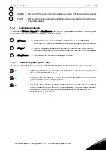
Figure 6-13. Positive/Negative logic
+24V
+24V
DIN1
DIN2
DIN3
CMA
DIN1
DIN2
DIN3
CMA
nk6 _16
Ground
Ground
Positive logic (+24V is the active signal) =
the input is active when the switch is closed
Negative logic (0V is the active signal) =
the input is active when the switch is closed.
Requires setting of jumper X3 to position
‘CMA/CMB isolated from ground’
Содержание FI4
Страница 1: ...vacon nxi inverters fi4 fi8 user manual ...
Страница 2: ......


