TROUBLESHOOTING
Service Manual M4 - M10
11.07.2002
Page
53
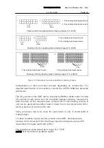
With new power board (CB00042, CB00055) layout it is possible to disconnect
DC+ from main circuit by pulling jumper X22 off and connect external power
supply to “AMP” connector X21. Remove always jumper from each power
board. With this power board it is not required to disconnect X8 and X19.
7.3.2.2 Checking of IGBTs
Visual checking:
At the first, look at power modules, connections and junctions for possible
destructive visible damages. Open exploded enclosure of the IGBT is relatively
common sign of the destructive failure in main circuit and due to failure
mechanism is easy to identify.
Cracked case of power component is easy to find if exists, however to find and
identify reason for the failure needs more than visible inspection.
If IGBT bridge after the visible checking cannot be judged to be failed,
advanced techniques have to be used.
Threshold voltage checking:
To check condition of IGBTs, digital multimeter with “diode checking mode” is
needed.
Line and motor leads disconnected, measure threshold voltages cross CE-
junctions of the IGBTs according instructions as in section 8.2.3 AC TO DC-
CONVERTER.
Checking of gate capacitance:
Remember ESD protection!
Procedure of checking gate capacitance will help to figure out condition of the
IGBT, suspected to be damaged.
In this procedure, capacitance meter is needed for measurement.
After the unit is unpowered, disconnect wire harnesses one by one from
connectors X9, X11 and X13 on the Power board and measure gate
capacitance from each IGBT.
The gate capacitance should be in range of 3 - 100nF. Value variates from type
to type, but when compared the values in one module, the value of
capacitance measured from upper leg IGBT (dual pack module) should no
variate more, than 20% of value measured from lower leg IGBT. Same values
Содержание CX
Страница 1: ......
Страница 33: ...TROUBLESHOOTING Service Manual M4 M10 11 07 2002 Page 33 ...
Страница 34: ...TROUBLESHOOTING Service Manual M4 M10 11 07 2002 Page 34 ...
Страница 148: ...SPARE PART LISTS Service Manual M4 M10 Page 148 ...


