


TROUBLESHOOTING
Service Manual M4 - M10
11.07.2002
Page
52
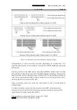
Voltage level from terminals X5, X6 on an Expander CB00019 (Extender
CB00119) board should be measured for checking up the offset error of CT. If
voltage exists, internal damage of the CT can be suspected.
For determination to replace the CT, measure operation voltages from the
terminal of the CTs.
For reference (DC-) can be found from base plate of Extender board regulator
N4.
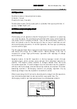
Functional checking:
Connect signal source 1Vrms to terminals X5 and X6 pins 6, 7 and 8 on the
Extender board (common at base plate of regulator N4). Repeat procedure for
each block in construction, if more than one. Waveform of the signal is free if
checking only current measurement of extender/extender board. To have
correct reading of the n3 current monitor page, sinusoid wave required.
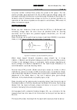
Three-phase signal recommended otherwise earth fault occurred (set
protection function temporarily off, parameter 7.4).
Measure signals from Control board terminal X2 pins 6, 7 and 8 to (DC-).
Value of the signals at terminal X2 shall be as follows:
M8
U(X2) = 1/2 * U(X5, X6)
M9
U(X2) = 1/3 * U(X5, X6)
M10 U(X2) = 1/4 * U(X5, X6)
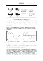
Look at value on monitoring display n3 (motor current) and compare it to
nominal rated current (constant torque rating) of the particular drive (correct
reading only if sinusoidal waveform is used).
Signal 1Vrms represents nominal value of the particular drive and the value
on the display should be as nominal.
NOTE! In case of 500V drive, 1V signal compares nominal current of 400V drive
(same power size). Adapter board is the same in 400V and 500V unit.
Units in power range
CX4 and CXL4, 315 - 400kW
CX5 and CXL5, 315 - 400kW
CX6,
90
-
315kW
Procedure for checking of operation as before described in section power
rating 110kW – 250kW (400, 500V), but additionally wire harness from terminal
X19 on Power board to gates of SCRs has to be disconnected.
Содержание CX
Страница 1: ......
Страница 33: ...TROUBLESHOOTING Service Manual M4 M10 11 07 2002 Page 33 ...
Страница 34: ...TROUBLESHOOTING Service Manual M4 M10 11 07 2002 Page 34 ...
Страница 148: ...SPARE PART LISTS Service Manual M4 M10 Page 148 ...