background image

4

vacon • 36

Power cabling

Local contacts: http://drives.danfoss.com/danfoss-drives/local-contacts/

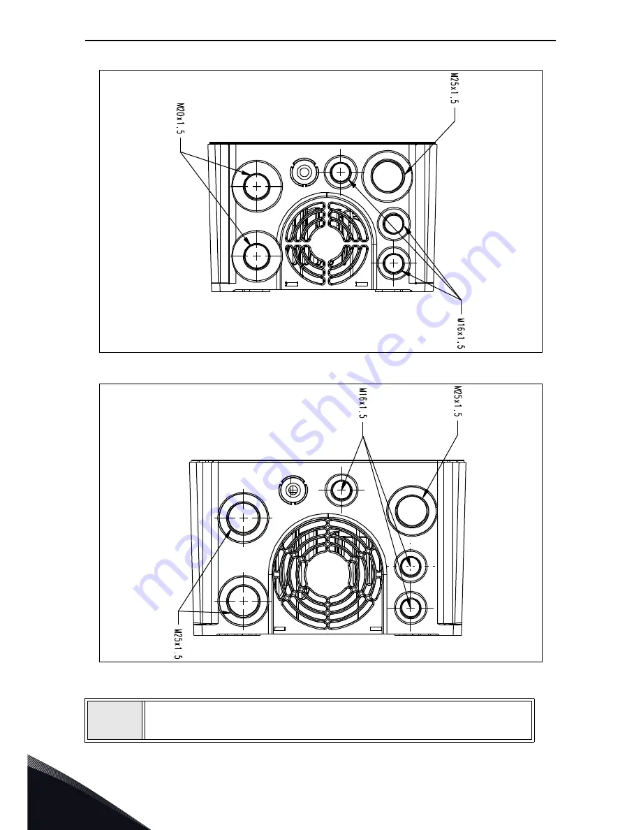
Figure 23.Cable entries, MU2.

Figure 24. Cable entries, MU3.

5

Cable glands must be made of plastic materials. They are used for sealing 
cables passing through cable entries to ensure the characteristics of the 
enclosure.

Содержание 20 x

Страница 1: ...vacon 20 x ac drives Installation Technical and Maintenance Manual ...

Страница 2: ......

Страница 3: ...uit breaker 26 4 2 UL standards on cabling 26 4 3 Description of the terminals 27 4 3 1 MU2 three phase version power connections 27 4 3 2 MU2 single phase version power connections 28 4 3 3 MU3 power connections 29 4 4 Cable dimensioning and selection 30 4 4 1 Cable and fuse sizes enclosures MU2 and MU3 30 4 4 2 Cable and fuse sizes enclosures MU2 and MU3 North America 31 4 4 3 Recommended fuse s...

Страница 4: ...formation on control connections 70 8 Options 72 8 1 VACON keypad with seven segment display 72 8 1 1 Mounting onto the drive 72 8 1 2 Text Keypad buttons 75 8 2 Text keypad 76 8 3 Menu structure 76 8 4 Using the keypad 77 8 4 1 Main menu 77 8 4 2 Resetting fault 78 8 4 3 Local Remote control button 78 8 4 4 Reference menu 78 8 4 5 Monitoring menu 79 8 4 6 Parameter menu 80 8 4 7 System Fault menu...

Страница 5: ... application 114 10 1 Danger 114 10 2 DC Fuse selection 114 10 3 Manufacturers of gPV fuses 115 10 4 Parallel diode selection 115 10 5 Photovoltaic system dimensioning 116 10 6 Grounding 117 10 6 1Pole Grounding 117 10 6 2Drive Grounding 117 10 7 AC grid connection 117 10 7 1More than one source of supply 117 10 7 2Toggle between AC and DC 117 10 8 External 24V supply 117 10 9 DC power connection ...

Страница 6: ...all operate and maintain the drive 1 1 Signs The cautions and warnings are marked as follows 1 2 Units The dimensions used in this manual conform to International Metric System units otherwise known as SI Système International d Unités units For the purpose of the equipment s UL certification some of these dimensions are accompanied by their imperial equivalents Table 1 Warning signs DANGEROUS VOL...

Страница 7: ...re starting any work on the connections of VACON 20 X Drive After expiration of this time use measuring equipment to absolutely ensure that no voltage is present Always ensure absence of voltage before start ing any electrical work The control I O terminals are isolated from the mains potential However the relay outputs and other I O terminals may have a dangerous control voltage present even when...

Страница 8: ...ctionalities including start inputs may change if parameters applications or software are changed Disconnect therefore the motor if an unexpected start can cause danger This is valid only if STO inputs are energized For prevention on unexpected restart use appropriate safety relay connected to the STO inputs The motor starts automatically after automatic fault reset if the autoreset function is ac...

Страница 9: ...fixed connection and provision of an additional terminal for a second pro tective grounding conductor of the same cross sectional area as the original protective grounding conductor Three screws for the three phase version are provided for the ORIGINAL protective grounding conductor the SECOND protective conductor and the MOTOR protective conductor the customer can choose the screw for each one Se...

Страница 10: ...unding conductor which does not form a part of the supply cable or cable enclosure must not in any case be less than 2 5 mm2 if mechanical protection is provided or 4 mm2 if mechanical protection is not provided For cord connected equipment provisions shall be made so that the protective groundingconductor in the cord must in the case of failure of the strain relief mechanism be the last conductor...

Страница 11: ...ou need to connect other circuits to the drive and test the complete assem bly Should you have any doubts or questions please contact your local VACON distributor Figure 3 Insulation system three phase version Please consider carefully the insulation system depicted in Figure 2 before con necting any circuit to the unit The control unit of VACON 20 X fulfils the insulation requirements of the stan...

Страница 12: ...ce has to be guaranteed between DVC A circuits and Mains reinforced insulation is required according to IEC 61800 5 1 This product can cause a d c current in the protective grounding conductor Where a residual current operated protective RCD or monitoring RCM device is used for protection in case of direct or indirect contact only an RCD or RCM of Type B is allowed on the supply side of this produ...

Страница 13: ...rent With de rating the unit can operate up to 50 C Figure 5 Temperature output current derating curve The AC drive is cooled down by air ventilation Therefore make sure that enough free space is left around the AC drive to ensure sufficient air circulation see for more details the mounting instruc tions on chapter 3 NOTE Up to 1 5 kW Voltage range 380 480V and 0 75 kW Voltage range 208 240V the d...

Страница 14: ...3L 0003 5 0016 5 CP Vacon 0020 1L 0004 2 0007 2 X Vacon 0020 3L 0004 2 0017 2 X Vacon 0020 3L 0003 4 0016 4 X Vacon 0020 3L 0003 5 0016 5 X Product Safety Functions Safe Torque Off EN 61800 5 2 2007 and Emergency stop EN 60204 1 2006 A1 2009 AC 2010 in extracts available only on three phase models Covered by this declaration is in conformity with the following directive s standard s or other norma...

Страница 15: ...Safety vacon 13 Local contacts http drives danfoss com danfoss drives local contacts 1 Figure 7 STO certificate ...

Страница 16: ...afety warning and caution information from http drives danfoss com knowledge center technical documentation REMARQUE Vous pouvez télécharger les versions anglaise et française des manuels produit contenant l ensemble des informations de sécurité avertissements et mises en garde applicables sur le site http drives danfoss com knowledge center technical documentation ...

Страница 17: ...agraph 2 4 Figure 8 VACON package label 440240 94 M163800526 70SCO01444 Danfoss A S 6430 Nordborg Denmark P2 3 kW 400 V 4hp 480 V IP66 U2 3AC 0 Input V 0 320 Hz I2 7 6 A U1 3AC 380 480 V 50 60 Hz I1 9 6 A Made in Italy POWER OUTPUT INPUT VACON SPA VACON0020 3L 0008 4 X SEBK 160928 FW0117V011 Marks Cust Ord No Application Firmware B ID S N Code Type AC DRIVE M16380052 6 70SC O0144 4 Vacon type code...

Страница 18: ...ered The format of the code is as follows VACON0020 3L 0009 4 X xxxx yyyy VACON This segment is common for all products 0020 Product range 0020 Vacon 20 3L Input Function 3L Three phase input 1L Single phase input 0009 Drive rating in ampere e g 0009 9 A See Table 27 and Table 29 for all the drive ratings 4 Supply voltage 2 208 240 V 4 380 480 V X IP66 Type 4X enclosure xxxx yyyy Additional codes ...

Страница 19: ...e MU3 VACON0020 3L 0011 2 X 2 2 kW 3 0 HP drive VACON0020 3L 0012 2 X 3 0 kW 4 0 HP drive VACON0020 3L 0017 2 X 4 0 kW 5 0 HP drive Supply voltage 1AC 208 240V MU2 VACON0020 1L 0004 2 X 0 75 kW 1 0 HP drive VACON0020 1L 0005 2 X 1 1 kW 1 5 HP drive VACON0020 1L 0007 2 X 1 5 kW 2 0 HP drive Supply voltage 3AC 380 480V MU2 VACON0020 3L 0003 4 X 0 75 kW 1 0 HP drive VACON0020 3L 0004 4 X 1 1 kW 1 5 H...

Страница 20: ...ive have been damaged during shipping please contact the cargo insurance company or the carrier in the first instance 2 4 Accessories After lifting the AC drive out check that the delivery is complete and the following accessories are included Figure 9 STO connector Table 4 Enclosure weights Enclosure size Weight kg lb MU2 3 4 7 5 MU3 6 0 13 2 Table 5 Content of accessory bag Item Quantity Purpose...

Страница 21: ...ied sticker 2 4 2 Disposal When the device reaches the end of its operating life do not dispose of it as a part of standard household garbage Main components of the product can be recycled but some need to be fragmented to separate different types of materials and components that need to be treated as special waste from electrical and electronic components To ensure environmentally sound and safe ...

Страница 22: ...ing plane is relatively even Both enclosure sizes can be mounted in any position Fix the drive with four screws or bolts depending on the unit size 3 1 Dimensions 3 1 1 Enclosure MU2 and MU3 Figure 11 VACON 20 X MU2 Enclosure size Dimensions W x H x D mm in MU2 169 2 x 294 7 x153 8 6 66 x 11 60 x 6 06 MU2 HMTX 169 2 x 294 7 x175 7 6 66 x 11 60 x 6 92 MU2 QDSS 169 2 x 294 7 x176 6 66 x 11 60 x 6 93...

Страница 23: ...ounting plane or machine enclosure and fixed with the screws recommended in Table 6 Recom mended screw or bolt size for MU2 and MU3 is M5 Enclosure size Dimensions W x H x D mm in MU3 205 2 x 375 2 x 180 5 8 08 x 14 77 x 7 11 MU3 HMTX 205 2 x 375 2 x 202 1 8 08 x 14 77 x 7 96 MU3 QDSS 205 2 x 375 2 x 200 0 8 08 x 14 77 x 7 87 Enclosure size Screw number Screw size MU2 4 M5 MU3 4 M5 Table 6 Screws ...

Страница 24: ...re of the AC drive Contact our factory for more information on required clearances in different installations Table 7 Min clearances around AC drive A Clearance left and right from the drive B Clearance above the drive C Clearance underneath the AC drive Figure 13 Installation space NOTE that if several units are mounted above each other the required free space equals B C see the Figure 14 Moreove...

Страница 25: ...Mounting vacon 23 Local contacts http drives danfoss com danfoss drives local contacts 3 Figure 14 Installation space when drives are mounted on top of each other B C Air deflector ...

Страница 26: ...nals marked with U V and W See principal connection diagrams in Figure 15 and Figure 16 See also Table for the cable recommendations for different EMC levels Figure 15 Principal connection diagram three phase version Only for 3 units Figure 16 Principal connection diagram single phase version U T1 V T2 W T3 M L1 L2 L3 DC R R DC Keypad Control Power unit U T1 V T2 W T3 M L N DC DC Keypad Control Po...

Страница 27: ...pped with compact low impedance shield and intended for the specific mains voltage MCCMK EMCMK or similar recommended Recommended cable transfer impedance 1 30MHz max 100mohm m See Figure 17 360º grounding of the shield with cable glands in motor end needed for EMC category C2 4 Screened cable equipped with compact low impedance shield JAMAK SAB ÖZCuY O or similar Figure 17 NOTE The EMC requiremen...

Страница 28: ... and Table 29 NOTE circuit breaker is not allowed in installations where C UL is required Only fuses are recom mended 4 2 UL standards on cabling To meet the UL Underwriters Laboratories regulations use a UL approved copper cable with a minimum heat resistance of 70 75 C Use Class 1 wire only The units are suitable for use on a circuit capable of delivering no more than 50 000 rms symmet rical amp...

Страница 29: ...version power connections Figure 18 Power connections MU2 three phase version Table 10 Description of VACON 20X MU2 power terminals Terminal Description L1 L2 L3 These terminals are the input connections for the power supply 230 VAC models can be supplied by single phase voltage by connecting to L1 and L2 terminals with derat ing of 50 U T1 V T2 W T3 These terminals are for motor connections PES 3...

Страница 30: ...tions MU2 single phase version Table 11 Description of VACON 20 X MU2 power terminals single phase version Terminal Description L N These terminals are the input connections for the power supply Single phase 230 VAC voltage has to be connected to L and N terminals U V W These terminals are for motor connections 11747_uk PES PE AC power supply Single phase 3AC Motor ...

Страница 31: ...2 Description of VACON 20 X power terminals Terminal Description L1 L2 L3 These terminals are the input connections for the power supply 230 VAC models can be supplied by single phase voltage by connecting to L1 and L2 terminals with derat ing of 50 U T1 V T2 W T3 These terminals are for motor connections PES PE AC power supply Single or Three phases 3AC Motor ...

Страница 32: ...be PVC isolated use only cables with concentric copper shield Max number of parallel cables is 9 When using cables in parallel NOTE HOWEVER that the requirements of both the cross sectional area and the max number of cables must be observed For important information on the requirements of the grounding conductor see chapter Grounding and earth fault protection of the standard For the correction fa...

Страница 33: ...oncentric copper shield Max number of parallel cables is 9 When using cables in parallel NOTE HOWEVER that the requirements of both the cross sectional area and the max number of cables must be observed For important information on the requirements of the grounding conductor see standard Underwriters Lab oratories UL508C For the correction factors for each temperature see the instructions of stand...

Страница 34: ...circuit capable of delivering not more than 50 000 rms symmetrical amperes 500 V max when protected by Class J or T fuses VACON 20 X is approved for group installation by UL provided the fuse in the main branch circuit is a 60 A class T or J fuse 300V or 600V AC maximum according to the drive rating It is possible to choose any combination of AC drives but you have to pay attention that the total ...

Страница 35: ...terminals for an optional external brake resistor For MU2 brake resistor wires with faston 6 3 mm have to be used For MU3 a PCB terminal block with push in spring cage connector is provided Stranded wires max 4 mm2 with ferrules should be used See Table 30 and Table 31 for the resistor ratings 4 6 Control cables For information on control cables see chapter Control unit cabling ...

Страница 36: ...and signal cables of other systems The maximum length for motor cables is 30 m The motor cables should cross other cables at an angle of 90 degrees If cable insulation checks are needed see chapter Cable and motor insulation checks Start the cable installation according to the instructions below Figure 21 Stripping of cables Distance between cables m Shielded cable m 0 3 50 1 0 200 1 Strip the mot...

Страница 37: ... Remove the plastic cover of the drive as shown in Figure 22 3 The cable entries consists of several openings available for the cables with ISO metric thread Open only the inlet holes where you need to run the cables 4 Choose the correct cable glands in compliance with CE rules according to drive and cable size as shown in the following pictures ...

Страница 38: ...anfoss com danfoss drives local contacts Figure 23 Cable entries MU2 Figure 24 Cable entries MU3 5 Cable glands must be made of plastic materials They are used for sealing cables passing through cable entries to ensure the characteristics of the enclosure ...

Страница 39: ...ble glands Enclosure size Gland screw type metric Tightening torque Nm lbs in MU2 M16 1 0 8 9 M20 2 0 17 7 M25 4 0 35 5 MU3 M16 1 0 8 9 M25 4 0 35 5 7 Flexible conduit plastic or metallic are used as raceway for wires and cables in accordance with the National Electrical Code 8 To connect NPT conduits to the metric threads of cable entries adapters must be used These adapters must first be connect...

Страница 40: ...ection of the threads Keep tension on the tape and wrap it several times working away from the end of the NPT pipe When you have finished wrapping the Teflon smooth the loose end down into the threads Screw the NPT to metric adapter on the cable entry using the proper tightening torque See Table 17 for more details Screw the NPT pipes on the adapters Table 17 Tightening torque of NPT adapters to m...

Страница 41: ... of the cable and fix all together Connect the phase conductors of the supply and motor cables into their respective terminals Form the rest of the cable shield of both cables into pigtails and make a grounding connection with the clamp Make the pigtails just long enough to reach and be fixed to the terminal no longer Table 18 Tightening torques of terminals Enclosure size Type Tightening torque P...

Страница 42: ...s danfoss com danfoss drives local contacts 4 8 Wiring way In the following picture an example of wire cabling is given Figure 27 Wiring example with three phase versions Input Line Motor output Relays I O terminals STO terminals Option board terminals ...

Страница 43: ...drives danfoss com danfoss drives local contacts 5 5 CONTROL UNIT 5 1 Opening the drives Figure 28 Open front cover of the drive control unit MU2 three phase version Figure 29 Open front cover of the drive control unit MU2 single phase version ...

Страница 44: ...5 vacon 42 Control unit Local contacts http drives danfoss com danfoss drives local contacts Figure 30 Open front cover of the drive control unit MU3 ...

Страница 45: ...components in control unit of MU2 three phase version Table 19 Locations of components in control unit Number Meaning 1 Control terminals A 20 2 STO terminals only in three phase version 3 Relay terminals 4 Option board terminals 5 STO Jumpers only in three phase version 6 DIP switches 7 Status LEDs 8 HMI connector RJ45 keypad connector 9 Optional brake resistor terminals 10 Supply voltage connect...

Страница 46: ... unit Local contacts http drives danfoss com danfoss drives local contacts Figure 32 Locations of the components in control unit of MU2 single phase version Figure 33 Location of the components in the control unit of MU3 ...

Страница 47: ... you will find the arrangement of the control I O and the relay terminals the general wiring diagram and the control signal descriptions The control board can be powered externally 24VDC 10 1000mA by connecting the external power source between terminal 6 and GND see chapter 5 3 2 This voltage is sufficient for param eter setting and for keeping the control unit active Note however that the values...

Страница 48: ...All signal descriptions are also given in Table 21 Figure 34 Control terminals 5 3 1 Control cable sizing The I O control and relays and STO cables must be screened multi core cables with the following cable sizes 0 14 1 5 mm2 without ferrules 0 25 1 5 mm2 with ferrules no plastic neck 0 25 1 5 mm2 with ferrules with plastic neck Find the tightening torques of the I O control and relays and STO te...

Страница 49: ...inal signals and connection example Standard I O terminals Terminal Signal A RS485_A Serial bus negative B RS485_B Serial bus positive 1 10 Vref Reference output 2 AI1 Analogue input voltage or current 3 GND I O signal ground 6 24Vout 24V aux voltage 7 DIN COM Digital inputs com mon 8 DI1 Digital input 1 9 DI2 Digital input 2 10 DI3 Digital input 3 4 AI2 Analogue input voltage or current 5 GND I O...

Страница 50: ... and connection example Relays terminals Terminal Signal 22 RO1 2 Relay output 1 23 RO1 3 24 RO2 1 Relay output 2 25 RO2 2 26 RO2 3 Table 23 I O terminal signals for the STO functions Safe Torque Off terminals Terminal Signal S1 Isolated digital input 1 inter changeable polarity 24V 20 10 15mA G1 S2 Isolated digital input 2 inter changeable polarity 24V 20 10 15mA G2 F Isolated feedback CAUTION Po...

Страница 51: ...rd In Figure 35 the view of Molex connector for the I O terminals is shown In the control unit the po sition of this connector is numbered with 11 as shown in Figure 31 Figure 32 and Figure 33 The type of this connector is Pico Clasp Wire to Board PCB Header Dual Row RIght Angle The code by Molex is 501571 2007 It mates with Pico Clasp Wire to Board Receptacle Housing crimp housing Dual Row 20 Cir...

Страница 52: ...ON 20 X termi nals is shown Table 24 I O remote connector description Pin number Signal Description 1 RS485_B Serial bus positive 2 DI2 Digital input 2 3 RS485_A Serial bus negative 4 DI3 Digital input 3 5 NC not connected 6 AI2 7 NC not connected 8 GND 9 10Vref 10 DO1 common for digital output 1 11 AI1 12 DI4 Digital input 4 13 GND 14 DI5 Digital input 5 15 24Vout 16 DI6 Digital input 6 17 DIN CO...

Страница 53: ...r of the drive there are 4 status LEDs See the picture below Figure 37 LED position on the MU2 cover Led PWR orange led means the drive is supplied by mains Led RUN green led means the drive is running Led FLT red led means the drive is experiencing a fault Led RDY orange led means the drive is ready and no fault is present When a Warning is active the led starts blinking ...

Страница 54: ...W2 and SW3 Analogue inputs can be used as either current inputs or voltage inputs The signal type is selected with two switches on the control board The switch SW2 is related to analogue input AI1 In position 1 the analogue input AI1 works in volt age mode In position 0 the analogue input works in current mode The default position for SW2 is 1 The voltage range is 0 10V and the current is 0 4 20 m...

Страница 55: ...easy upgrade of the hardware structure of an industrial network without the need for significant changes in the software A device can also communicate with several Modbus nodes at once although they are connected with differ ent interface types without the need to use a different protocol for every connection Figure 39 Basic structure of Modbus frame On simple interfaces such as RS485 the Modbus m...

Страница 56: ...and B See Figure 40 Figure 40 Position of the RS485 terminals on the I O standard terminal connector MU2 control unit example Table 25 Connections and communications Interface RS 485 Data transfer method RS 485 MS TP half duplex Transfer cable STP shielded twisted pair type Belden 9841 or similar Connector 2 5 mm2 Electrical isolation Functional Modbus RTU As described in Modicon Modbus Protocol R...

Страница 57: ...e aluminium cable shield 2 Then connect the cable to its appropriate terminals on VACON 20 X AC drive standard terminal block terminals A and B A negative B positive 3 Using the cable clamp included in the supply of the drive ground the shield of the RS485 cable to the enclosure of the AC drive 4 If VACON 20 X drive is the last device on the bus the bus termination must be set Locate the switches ...

Страница 58: ...ted to the mains even if the motor is not running The control I O terminals are isolated from the mains potential However the relay outputs may have a dangerous control voltage present even when VACON 20 X drive is disconnected from the mains Do not make any connections to or from the AC drive when it is connected to the mains After disconnecting the AC drive from the mains wait until the indicato...

Страница 59: ... power cables see chapter 4 4 Check that the shields of the shielded cables are connected to protective earth marked with Check the tightening torques of all terminals Check that the wires do not touch the electrical components of the drive Check that the common inputs of digital input groups are connected to 24V or ground of the I O terminal Check the quality and quantity of cooling air Check the...

Страница 60: ...s EMC protected according to class C1 or C2 you need to modify the EMC protection of the AC drive to EMC level T C4 This is done as described below 6 2 1 Changing EMC protection class MU2 three phase version Figure 41 Changing of the EMC class in MU2 control unit Warning Do not perform any modifications on the AC drive when it is connected to mains 1 Remove the three screws on the EMC plate from t...

Страница 61: ...danfoss drives local contacts 6 Figure 42 Changing of the EMC class in MU2 control unit 2 Remove the EMC plate from the control unit Then lift the plate with pliers to dis connect the EMC plate from the ground See Figure 42 Then reconnect the EMC plate to the unit ...

Страница 62: ...ntacts http drives danfoss com danfoss drives local contacts 6 2 2 Changing EMC protection class MU2 single phase version Figure 43 Changing the EMC class in the MU2 single phase version 1 Remove the EMC screw as shown in the Figure 43 ...

Страница 63: ... Figure 44 CAUTION Before connecting the AC drive to mains make sure that the EMC pro tection class settings of the drive are appropriately made NOTE After having performed the change write EMC level modified on the sticker included in the VACON 20 X delivery see below and note the date Unless al ready done attach the sticker close to the name plate of the AC drive Product modified Date Date Date ...

Страница 64: ...between each phase conductor and the protective ground conductor The insulation resistance must be 1MΩ at ambient temperature of 20 C 3 Motor insulation checks Disconnect the motor cable from the motor and open the bridging connections in the motor connection box Measure the insulation resistance of each motor winding The measurement voltage must equal at least the motor nominal voltage but not ex...

Страница 65: ...ce intervals Table 26 Maintenance interval Maintenance action Regularly and according to general maintenance interval Check tightening torques of termi nals 6 24 months depending on environment Check input and output terminals and control I O terminals Check for corrosion on terminals and other surfaces Check the heatsink for dust and clean if necessary 6 10 years Change the main fan 12 24 months ...

Страница 66: ...ACON 20 X supply voltage 208 240V Mains Voltage 3AC 208 240V 50 60 Hz AC drive type Input current A Loadability Motor shaft power 230V 240V Rated continuous current IN A 50 overload current A Max current IS kW HP MU2 0004 4 3 3 7 5 6 7 4 0 75 1 0 0005 6 8 4 8 7 2 9 6 1 1 1 5 0007 8 4 7 0 10 5 14 0 1 5 2 0 MU3 0011 13 4 11 0 16 5 22 0 2 2 3 0 0012 14 2 12 5 18 8 25 0 3 0 4 0 0017 20 6 17 5 26 3 35 ...

Страница 67: ...ample If the duty cycle requires 150 rated current for 1 min in every 10 min the remaining 9 min must be at rated current IN or less Figure 45 High overload Table 29 Power ratings of VACON 20 X supply voltage 380 480V Mains Voltage 3AC 380 480V 50 60 Hz AC drive type Input current A Loadability Motor shaft power 400V 480V Rated continuous current IN A 50 overload current A Max current IS kW HP MU2...

Страница 68: ...only in three phase ver sion Recommended minimum brake resistor values for VACON 20 X AC drives Table 30 Brake resistor ratings 208 240V Mains Voltage 3AC 208 240 V 50 60 Hz Enclosure size Type Minimum Resistance recommended Ohm MU2 0004 50 0005 50 0007 50 MU3 0011 25 0012 25 0017 25 Table 31 Brake resistor ratings 380 480V Mains Voltage 3AC 380 480 V 50 60 Hz Enclosure size Type Minimum Resistanc...

Страница 69: ...ut voltage 3AC 0 Uin Rated output current IN Ambient temperature max 40 C See Table 27 and Table 29 Overload output current 1 5 x IN 1 min 10 min Starting current IS for 2 s every 20 s IS 2 0 IN Output frequency 0 320 Hz Frequency resolution 0 01 Hz Protection class I Motor characteristics AC squirrel cage motors Permanent magnet motors Cable type Screened motor cable Cable maximum length 30 m Con...

Страница 70: ... is suitable for outdoor use because of dust tight enclosure to numeral 6 acc to IEC 60529 Altitude 100 load capacity no derating up to 1 000m derating 1 100m at 1 000 3 000m Degree of protection IP66 Type 4X IP65 when used with Simple Operator Panel QDSH Stationary vibration Sinusoidal 3 Hz f 8 43 Hz 7 5mm 8 43 Hz f 200 Hz 2g 3M6 acc to IEC 60721 3 3 Shock Bump 25g 6ms 3M6 acc to IEC 60721 3 3 Di...

Страница 71: ... 0 8775 supply voltage Supply voltage 240 V Trip limit 211 V Supply voltage 400 V Trip limit 351 V Supply voltage 480 V Trip limit 421 V Earth fault protection Yes Mains supervision Yes Motor phase supervision Yes not available in 1 phase version Overcurrent protection Yes Unit overtemperature protection Yes Motor overload protec tion Yes These devices provide motor overload protection at 105 of f...

Страница 72: ... an external power supply with a current limiter or fuse protected to supply the control unit and fieldbus for backup purposes Dimensioning max 1000mA control unit 7 DIN COM Common for digital inputs Connected to GND with dip switch SW1 See Chapter 5 8 Digital input 1 Positive or negative logic Ri min 4kΩ 15 30V 1 0 5V 0 9 Digital input 2 10 Digital input 3 4 Analogue input voltage or current Anal...

Страница 73: ... control voltage from the output relays the control circuitry must be powered with a separate isolation transformer to limit short circuit current and overvoltage spikes This is to prevent welding on the relay contacts Refer to standard EN 60204 1 section 7 2 9 Switching capacity 250VAC 3A only earthed network allowed 23 24 Relay output 2 Switching capacity NO 250VAC 5A NC 250VAC 3A only earthed n...

Страница 74: ...for VACON 20 X The control keypad is the interface between the VACON 20 X AC drive and the user Figure 46 Text keypad 8 1 1 Mounting onto the drive Figure 47 Drive and the optional keypad kit The optional keypad kit includes keypad and cable Order code Description Type of option VACON PAN HMTX MC06 X Handheld Magnetic fixing IP66 text keypad w cable l 1m 39 37 inches Loose option ...

Страница 75: ...Options vacon 73 Local contacts http drives danfoss com danfoss drives local contacts 8 Figure 48 Disconnection of the HMI cap from the drive Figure 49 Mounting of the keypad ...

Страница 76: ...ns Local contacts http drives danfoss com danfoss drives local contacts Figure 50 Tighten the two screws maximum tightening torque 0 5 Nm of the keypad cable to the enclosure of the drive Keypad mounted onto the drive ...

Страница 77: ...te of the drive and to set the AC drive s parameters The button section of the text keypad is shown in the following picture Figure 51 Keypad buttons Scroll menu up Increase value Scroll menu down Decrease value Move cursor left Move cursor right Move backward in menu Exit edit mode Reset faults with long press Change control place Stop button Start button Enter active level item Confirm selection...

Страница 78: ...n arrows to move be tween the menus Enter the group item by pressing the OK button and return to the former level by pressing the Back Reset button The arrows on the left of the display show the active menu In Figure 52 the REF menu is active The table below shows the structure of the main menu Table 35 Keypad menus Reference REF Reference from Keypad Monitor MON Monitoring values Parameters PAR A...

Страница 79: ...O P READ Y RUN M ON FWD RE V I O KE YP AD BUS EF PAR FAULT ALARM S TO P RE AD Y RUN MO N FWD RE V I O KE YP AD BUS REF PAR FAULT ALARM S TO P RE AD Y RUN MO N FWD RE V I O KE YP AD BU S REF PAR FAULT ALAR M S TO P RE ADY RU N MO N FW D RE V I O KE YP AD BUS R EF PAR FAU LT ALAR M STO P READ Y RU N MO N PRESS PRESS PRESS PRESS PRESS FWD REV I O KEY PAD BUS RE F M O N PAR FAULT ALAR M S TOP RE ADY R...

Страница 80: ...he selected control place can be seen on the status bar of the keypad Remote control place I O and Fieldbus can be used as remote control places Local control Keypad is always used as control place while in local control Local control has higher priority than remote control Switching between Local and Remote Control can be done by pressing the LOC REM button on the keypad 8 4 4 Reference menu Figu...

Страница 81: ...elected signal and its value are alternating in the display by pressing OK button NOTE Turn on drive power arrowhead of main menu is at MON V x x or monitor parameter value of Vx x is displayed in Panel Display Vx x or monitor parameter value of Vx x is determined by the last show status before power shut down OK OK OK 1 2 3 5 4 FAULT ALARM STOP READY RUN REF MON PAR REF MON PAR FAULT ALARM STOP R...

Страница 82: ...alue is numerical and change then the value with the arrow but tons up down 4 Confirm change with OK button or ignore change by returning to previous level with Back Reset button OK OK 2 Press Right to browse otherPar group 4 Press OK button to enter edit mode 3 Press down button to browse P3 4 5 Press Up Down to change value OK 6 Press OK to confirm FAULT ALAR M S TO P RE ADY RU N FAULT ALAR M S ...

Страница 83: ...Fault menu OK Press OK to enter V1 1 1 Press Left Right button to browse other groups 2 Press down to browse other active faults 3 FAULT ALARM STOP FWD REV I O KEYPAD BUS READY RUN OK Press OK to select one fault to browse its time 4 FAULT ALARM STOP READY RUN FWD REV I O KEYPAD BUS Browse for fault code C xx subcode Id xx days d xx hours H xx minutes M xx 5 FAULT ALARM STOP READY RUN FWD REV I O ...

Страница 84: ...atically to the fault menu if no button is pressed in 10 seconds The fault code subcode and the operating day hour and minute values at the fault instant are shown in the value menu operating hours displayed reading Active faults Fault history Menu Function Note Active faults When a fault faults appear s the display with the name of the fault starts to blink Press OK to return to the Diagnostics m...

Страница 85: ...r motor Check motor cables and motor 84 MPI communication crc error Reset the fault and restart Should the fault re occur contact the distributor near to you 89 HMI receives buffer overflow Check PC drive cable Try to reduce ambient noise 90 Modbus receives buffer overflow Check Modbus specifications for time out Check cable length Reduce ambient noise Check baudrate 8 System Fault 93 Power identi...

Страница 86: ...lot Try to reduce ambient noise Should the fault re occur contact the distributor near to you 108 Option board SPI queue full Check contacts in option board slot Try to reduce ambient noise Should the fault re occur contact the distributor near to you 111 Parameter copy error Check if parameter set is compatible with drive Do not remove Keypad until copy is finished 113 Frequency detective timer o...

Страница 87: ...orrect amount and flow of cooling air Check the heatsink for dust Check the ambient temperature Make sure that the switching fre quency is not too high in relation to ambient temperature and motor load 15 Motor stalled Motor is stalled Check motor and load Insufficient motor power check motor stall protection parametriza tion 16 Motor overtemperature Motor is overloaded Decrease motor load If no m...

Страница 88: ...mes sages The input is active Check the programming and check the device indicated by the error message Check the cabling for the respective device as well 52 Keypad Communication fault The connection between the con trol keypad and the AC drive is bro ken Check keypad connection and keypad cable 53 Fieldbus communication fault The data connection between the fieldbus master and fieldbus board is ...

Страница 89: ...or input and two relay outputs OPT B4 V I O expander board with one galvanically isolated analogue input and two galvanically isolated analogue outputs standard signals 0 4 20mA OPT B5 V I O expander board with three relay outputs OPT B9 V I O expander board with five 42 240 VAC digital inputs and one relay output OPT BF V I O expander board with ana logue output digital output and relay output On...

Страница 90: ...3 example NOTE Do not add or replace option boards or fieldbus boards on an AC drive with the power switched on This may damage the boards 1 Remove the HMI cap and open the cover of the drive The relay outputs and other I O terminals may have a dangerous control voltage present even when the drive is disconnected from mains 2 Remove the option slot cover ...

Страница 91: ...Options vacon 89 Local contacts http drives danfoss com danfoss drives local contacts 8 Figure 59 Removing the option slot cover ...

Страница 92: ... board says dv dual voltage This indicates that the board is compatible with VACON 20 X See below NOTE Incompatible boards cannot be installed on VACON 20 X Compat ible boards have a slot coding that enables the placing of the board see above 4 Install the option board into the slot as shown in the picture below Slot coding OPT dv 9116 emf ...

Страница 93: ...Options vacon 91 Local contacts http drives danfoss com danfoss drives local contacts 8 Figure 60 Option board installation 5 Mount the option slot cover ...

Страница 94: ...8 vacon 92 Options Local contacts http drives danfoss com danfoss drives local contacts Figure 61 Mounting of option slot cover remove the plastic opening for the option board ter minals ...

Страница 95: ...gure 62 Figure 62 The mains switch option spare kit MU2 example Table 38 Mains switch kit content Enclosure size Description and type code Item Quantity MU2 3 phase version MU2 QDSS option spare kit 60S01128 Main switch 40A NLT40 assembly 1 MU2 cover for main switch 1 M4x14 screw 2 M5x23 screws 4 MU2 1 phase version MU2 QDSS option spare kit 60S01234 Main switch 40A NLT40 assembly 1 MU2 cover for ...

Страница 96: ...he supply cable to the Mains switch passing through the cable gland from the bottom side use the cable gland for sealing the cable to the drive and then through the terminal box as shown in the figure below 4 Place the Mains switch with the cables inside the drive and fix it with its screws 5 Connect the cables from the Mains switch to the line terminal The cables have to be connected to the termi...

Страница 97: ...cal contacts http drives danfoss com danfoss drives local contacts 8 Figure 64 Mains switch and cables connected MU2 3 phase example 7 Connect the GROUND wire to the proper terminal see the yellow green cable on Figure 64 ...

Страница 98: ... contacts http drives danfoss com danfoss drives local contacts Figure 65 Mount the plastic cover 8 Mount the plastic cover onto the drive with its screws and HMI cap the instal lation process has been completed See Figure 65 ...

Страница 99: ...ded This option can be mounted on the front side of the drive See Figure 66 Figure 66 The Simple operator panel option spare kit MU2 example Table 39 Simple operator panel kit content Enclosure size Description and type code Item Quantity MU2 3 phase version MU2 QDSH option spare kit 60S01208 Main switch 40A NLT40 and operator panel assembly 1 MU2 cover for main switch 1 M4x14 screw 2 M5x23 screws...

Страница 100: ...60S01209 Main switch 40A NLT40 and operator panel assembly 1 MU3 cover for main switch 1 M4x14 screw 2 M5x23 screws 6 1 Remove the HMI cap and the cover from the drive See the Figure 67 2 Open only the inlet holes where you need to run the cables Cables pass through this inlet hole Table 39 Simple operator panel kit content Enclosure size Description and type code Item Quantity ...

Страница 101: ...the cable gland for sealing the cable to the drive and then through the terminal box as shown in the figure below 4 Place the Simple Operator panel assembly with the cables inside the drive and fix it with its screws 5 Connect the cables from the Mains switch to the line terminals The cables have to be connected to the terminals L1 L2 and L3 NOTE For single phase version connect BLU cable to N and...

Страница 102: ... panel Standard I O terminals Terminal Signal A RS485_A Serial bus negative B RS485_B Serial bus positive 1 10 Vref Reference output 2 AI1 Analogue input voltage or current 3 GND I O signal ground 6 24Vout 24V aux voltage 7 DIN COM Digital inputs com mon 8 DI1 Digital input 1 9 DI2 Digital input 2 10 DI3 Digital input 3 4 AI2 Analogue input voltage or current 5 GND I O signal ground 13 DO1 Digital...

Страница 103: ... 24V auxiliary voltage YELLOW wire 6 digital input DI1 WHITE wire 8 digital input DI2 GREY wire 9 11 Mount the plastic cover onto the drive with its screws use torque 2Nm and the HMI cap the installation process has been completed See Figure 69 Function Description Wire colors Terminal Table 41 Simple operator panel connection description ...

Страница 104: ...ompliance with accepted practice and regulations at the time of writing However the end product system designer is responsible for ensuring that the end system is safe and in compliance with relevant regulations When a permanent magnet motor is used and in case of a multiple IGBT power semi conductor failure when the STO option energizes the drive outputs to the off state the drive system may stil...

Страница 105: ...g table Table 42 Safety Standards Standards IEC 61508 Parts 1 7 EN 61800 5 2 EN 62061 ISO 13849 1 EN 954 1 IEC 60204 1 Table 43 Four different STO levels see 9 5 1 STO inputs STO feedback Cat PL SIL Both dynamically used Used 4 e 3 Both statically used Used 3 e 3 Connected in parallel Used 2 d 2 Connected in parallel Not used 1 c 1 Table 44 SIL values see 9 5 1 STO inputs STO feedback PFH PFDav MT...

Страница 106: ...y F F terminals The values assumed by the STO output feedback are indicated in the following table The diagram below is a conceptual schematic diagram and is presented to illustrate the safety function with relevant safety components only shown Figure 70 STO function principle Only for 3 units Table 45 Values of the STO output feedback and torque on the motor Only one channel is preventing the dri...

Страница 107: ...reaction time of the STO function is the amount of time which passes from the moment in which the STO is demanded until the system is in the Safe State For VACON 20 X the reaction time is 20 ms maximum Table 46 Electrical data Technical information Technical values Maximum voltage 30 V Typical input current at 24V 10 15 mA Logic threshold according to IEC 61131 2 15V 30V 1 0V 5V 0 Response time at...

Страница 108: ...l standards and regulations should be always followed in the final design Table 47 STO connector and data signals Signal Terminal Technical information Data STO1 S1 Insulated digital input 1 interchangeable polarity 24V 20 10 15 mA G1 STO 2 S2 Insulated digital input 2 interchangeable polarity 24V 20 10 15 mA G2 STO feedback F Insulated digital output for STO feedback CAUTION Polarity must be resp...

Страница 109: ...ut according to the following picture where the inputs are released with delay in turn The dynamic use of the STO inputs allows detecting faults that may otherwise accumulate Figure 72 An emergency push button connected to the STO inputs does not assure the same quality because no fault detection is performed at a sufficient frequency once a day is recommended The external safety device which forc...

Страница 110: ...s to monitor the STO function in accordance with the Table 45 The device has to periodically de energize the STO inputs and it has to verify that the STO output feedback assumes the expected value Any difference between the expected and the real value has to be considered as a failure and has to drive the system into a Safe State In case of failure check the wiring If the fault recognized by the e...

Страница 111: ...apply 9 5 3 Safety Capability Cat 2 PL d SIL 2 The safety capability is reduced to Cat 2 PL d SIL 2 if the STO inputs are connected in parallel no redundancy of the STO inputs The STO feedback has to be used The same warnings as 9 5 1 apply The picture below shows an example of connection for the STO function The external device has to be connected with 4 wires to the drive Figure 74 STO Example w...

Страница 112: ...tor stops by coasting Figure 75 STO example without automatic monitoring of the feedback and STO inputs connect ed in parallel Only for 3 units The choice of using the STO inputs without the automatic monitoring of the output feedback does not allow the other safety capabilities to be achieved The standards for functional safety require that functional proof tests are performed on the equipment at...

Страница 113: ...the system to ensure that the use of the STO function is safe and according to the local regulations Include in the assessment an examination of whether the use of external devices such as a mechanical brake are required Check if the switch if used has been chosen according to the required safety perfor mance target SIL PL Category set during the risk evaluation Check if the external device for au...

Страница 114: ... device F30 is displayed even after this has been released Reset the fault through a digital input or from the keypad It is possible that a new start command is required for the restart depending on the applica tion and your parameter settings Before testing the STO function make sure that the checklist Table 49 is inspected and completed When STO function is demanded the drive always generates a ...

Страница 115: ... any failure in safety functions including STO contact your local VACON supplier NOTE See Table 36 for detailed fault code descriptions If any service or repair has to be conducted on the drive installed please inspect the checklist given in Table 49 During maintenance breaks or in case of service repair ALWAYS make sure that the STO function is available and fully functional by testing it Table 5...

Страница 116: ... 2579 standard See table below for recommended fuse sizes The terminals are live when the VACON 20 X Drive is connected to a photovoltaic system Photovoltaic cells generate DC voltage even at low intensity of sunlight Wait 60 seconds until the drive is discharged before switching between AC and DC supply photovoltaic system and vice versa Table 51 Fuse characteristics Fuse type Min Voltage rating ...

Страница 117: ...Table 54 Recommended fuse sizes Mains voltage 3AC 380 480V 50 60 Hz up to 800V in VDC Enclosure size AC drive type Rated continuous current A IEC60269 6 Fuse size A UL 2579 Fuse size A MU3 0009 9 0 16 16 0012 12 0 20 25 0016 16 0 30 30 Table 55 Diode specification Mains voltage 3AC 208 240V 50 60 Hz up to 400V in VDC AC drive Diode specifications Enclosure size AC drive type min IFav A Min Voltage...

Страница 118: ...0 V 0012 28 0016 36 Table 58 VACON 20 X 208 240V 3AC 50 60Hz DC link input ratings Enclosure size AC drive type DC supply V Max Recommended PV Array Power kW MU3 0011 234 400VDC No tolerance permissible 0 4 4 0012 6 0 0017 8 0 Table 59 VACON 20 X 208 240V 1AC 50 60Hz DC link input ratings Enclosure size AC drive type DC supply V Max Recommended PV Array Power kW MU2 0004 234 400VDC No tolerance pe...

Страница 119: ... AC input are used e g in case of not sufficient energy from the photo voltaic system it is not allowed to switch directly between AC and DC supply When switching from one supply to the other it is mandatory to wait until the drive is discharged The discharge time and subsequently the minimum delay to switch between the supplies is 30 seconds Minimum AC DC switchover delay 60s 10 8 External 24V su...

Страница 120: ...ication Local contacts http drives danfoss com danfoss drives local contacts 10 9 DC power connection Figure 76 Example of the power connections MU2 1AC 11744_uk DC switch protection diode DC fuses 3AC PE DC DC power supply DC PES ...

Страница 121: ...lication vacon 119 Local contacts http drives danfoss com danfoss drives local contacts 10 Figure 77 Example of the power connections MU3 11744_uk DC switch protection diode DC fuses 3AC PE DC DC power supply DC PES ...

Страница 122: ...Document ID DPD00992H Rev H Vacon Ltd Member of the Danfoss Group Runsorintie 7 65380 Vaasa Finland www danfoss com ...

Отзывы: