


Apartment
Intercom System
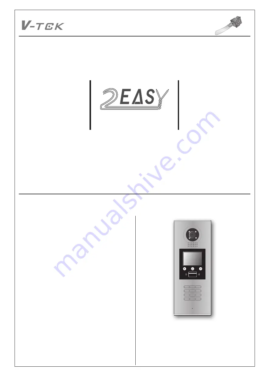
2-wire series
2 EAS
Y
1
2
3
6
5
4
7
8
9
#
0
*
RF CARD
CONTENTS
INTRODUCTION.
..........................................................................
2
Installation Guide.
......................................................................
2
CONFIGURATION.
.......................................................................
4
Debug
Mode
.
.............................................................................
4
Work Mode.
................................................................................
8
Software Update.
.......................................................................
10
Ringtone
Update.
......................................................................
10
UI Update.
..................................................................................
11
Namelist Update.
........................................................................
12
by SD Card.
.............................................................................
12
by DT-Config.
...........................................................................
13
DMR18S TECHNICAL MANUAL
DigiOpen


