background image

Your Reliable Partner in Industrial IoT

UTEK TECHNOLOGY

Page 11

Load default

Recover to default

Update firmware

Device firmware online upgrade

Save & reboot

Save configuration & reboot the device

Logout

Logout the interface

4 Basic

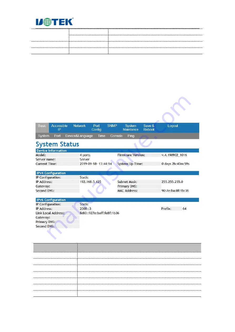
4.1 System Status

1. Interface Description

The interface shows the system information & IP config information of the device directly. The
interface is shown as below:

2. Keyword Explanations

Configuration item

Meaning

Model

Device tag management

Server name

Device network identification

Hardware version

Current hardware version information

Firmware version

Current firmware version information

System up time

How long the device used

Current time

Show current PC time

IP configuration

Show IP configuration

Содержание UT-600 Series

Страница 1: ... Product Manual Model UT 600X series Sep 15 2019 Version V1 0 UTEK TECHNOLOGY SHENZHEN CO LTD Add Floor 8 10 Building 7 Skyworth Innovation Valley No 8 Tangtou No 1 Road Shiyan Street Shiyan Old Street Bao an District Shenzhen Tel 86 755 81202008 Fax 86 755 27886083 Http www uotek com ...

Страница 2: ... Multi host Mode Max 4 host 4 2 Hardware Description 5 2 1 LED Indication 5 2 2 Serial Port Pin Assignment 5 2 2 1 UT 600X Serial Port PIN Assignment RJ45 5 2 2 2 UT 600XMT PIN Assignement RS 485 422 5 2 2 3 UT 600X 10 100M Ethernet Port PIN Assignment RJ45 6 2 3 Ethernet Port Definition 6 2 4 Specification 7 2 5 Packing 8 3 Login the Webpage 9 3 1 Login Web Managed Client 9 3 2 Web Interface 10 3...

Страница 3: ... b Fail to open COM port 31 c Data transmission failure 31 d Forget the password 31 e The data transmission is error codes 3 f Serial device server worked as a dial up server the connection has been established normally but the client PC with IE in the address column input domain name to open the web page it can not open but if IP address was input in the address column it can open 32 g Serial dev...

Страница 4: ... 39 13 1 8 Export Settings 40 13 1 9 Firmware Update 41 13 1 10 Open in Browser 41 13 2 COM Mapping 42 13 2 1 Create COM 42 13 2 2 Remove COM 43 13 2 3 Modify COM 43 13 2 4 Enable COM 43 13 2 5 Disable COM 44 13 2 6 Import COM List 44 13 2 7 Export COM List 45 13 3 Options 45 13 4 About 45 13 5 Exit 46 ...

Страница 5: ...Your Reliable Partner in Industrial IoT UTEK TECHNOLOGY Page 5 Revision History Date Version Description 2019 09 15 V 1 0 ...

Страница 6: ...theoretical principles practical skills and specialized knowledge of network device protocols and interfaces related to networking At the same time you must have the work experience of graphical user interface command line interface simple network management protocol and Web browser Convention This manual adopts the following GUI conventions GUI Description Explanation The necessary complements an...

Страница 7: ...supports gateway and proxy server can transfer data over the Internet It provides data bidirectional transparent transmission realize serial port to TCP IP function users do not need to make any changes to the original system It supports ARP IP TCP HTTP ICMP SOCKET UDP and other protocols All programs provide set up wizard easy to operate UT 6001 Series UT 6002 Series UT 6004 Serial UT 6008 Series...

Страница 8: ... means that using these serial ports is like using a local COM port on the host and means that all existing software or communication modules that are applied to the original serial port device can be used directly without modification Supports ARP Terminal server parameter configuration It can be configured via web connection to a terminal server Supports software upgrade 1 2 3 Security Feature U...

Страница 9: ...Your Reliable Partner in Industrial IoT UTEK TECHNOLOGY Page 4 1 3 2 Point to Point Mode 1 3 3 Point to Multi point Mode Max 4 clients 1 3 4 Multi host Mode Max 4 host ...

Страница 10: ...or Power indicator 2 port Data transceiver indicator 1 port Data transceiver indicator Model No 1st 2nd UT 6004 UT 6008 Running indicator Power indicator 2 2 Serial Port Pin Assignment 2 2 1 UT 600X Serial Port PIN Assignment RJ45 RJ45 RS 232 RS 485 HALF RS 422 FULL 1 TXD DATA TXD 2 RXD DATA TXD 3 RTS RXD 4 CTS RXD 5 DSR 6 GND GND GND 7 DTR 8 2 2 2 UT 600XMT PIN Assignement RS 485 422 3 81 termina...

Страница 11: ... be less than 100m 100Mbps connection adopts 100 Ω line cat 5 and 10Mbps connection adopts 100 Ω cat 3 cat 4 cat 5 The RJ45 port supports auto MDI MDI X For MDI connection pins 1 2 3 and 6 are connected accordingly For MDI X port of serial device server it adopts cross line 1 3 2 6 3 1 6 2 The 10Base T 100Base TX pin definitions in MDI MDI X applications are shown as below MDI X Direct line RJ45 E...

Страница 12: ...op bit 1 1 5 2 Flow control RTS CTS XON XOFF Port style RJ45 terminal block Port protection Contact 6KV air 8KV ESD protection surge 10 700us common mode differential mode 0 5KV Signal RS232 RXD TXD DTR GND DSR RTS CTS RS422 TXD RXD TXD RXD GND RS485 Data Data Ethernet port Transmission rate 10 100M auto negotiation Port style RJ45 Port protection Built in 2KV magnetic isolation surge 10 700us com...

Страница 13: ... DC12V 1A 1 set RS 232 485 422 RJ 45 output UT 6002MT 1 set DC12V 1A 1 set RS 485 422 3 81 terminal block output UT 6002 PD 1 set RS 232 485 422 RJ 45 POE UT 6002MT PD 1 set RS 485 422 3 81 terminal block output POE power UT 6002 5V 1 set DC5V 2A 1 set RS 232 485 422 RJ 45 5V power UT 6002MT 5V 1 set DC5V 2A 1 set RS 485 422 3 81 terminal block output 5V power UT 6002 48V 1 set 1 set RS 232 485 42...

Страница 14: ...r name is admin and the password is admin Click the login button to check the device system status information Explanations 1 When login the device the IP network segment of PC should be consistent with the serial device server network segment 2 When login at the first time the IP address of PC is set to 192 168 1 x x represents 1 254 except 125 and the subnet mask is set to 255 255 255 0 but the ...

Страница 15: ...cessible IP network config port config SNMP config system maintance save reboot logout It is shown as below Menu item Submenu Description Basic System status Show product information running information Port status Show all the ports parameters Device language Show the device name language Time setup Set timezone time Console setup Enable or disable Web Telnet access PING Ping operation to the tar...

Страница 16: ...ption The interface shows the system information IP config information of the device directly The interface is shown as below 2 Keyword Explanations Configuration item Meaning Model Device tag management Server name Device network identification Hardware version Current hardware version information Firmware version Current firmware version information System up time How long the device used Curren...

Страница 17: ... as below 4 3 Device Language 4 3 1 Interface Description 1 Interface Description The user can check and set the device name and language it is shown as below 2 Keyword Explanations Configuration item Meaning Server name Server name Menu language Select the language 3 Operation Steps Step 1 Click Basic enter Device setup Step 2 Set the parameter click Apply Step 3 If need to set it as default clic...

Страница 18: ...erver IP Time Zone Default is 08 00 3 Operation Steps Step 1 Click Basic enter time setup Step 2 Set the parameters click Apply Step 3 If need to set it as default click save reboot Apply 4 3 3 Console Setup 1 Interface Description Users can check current Settings via web and Telnet login When the TELNET service is enabled the TELNET terminal can connect to the serial device server via the TELNET ...

Страница 19: ...on IP command can be used under the system management view 3 If the terminal PC and the serial device server are connected to the same LAN its IP address must be set in the same network segment Otherwise the terminal and the serial device server must cross routers If the above conditions are met TELNET can be used to log in to the serial device server for configuration 2 Example Before login the s...

Страница 20: ... on the network it send a packet to the target IP address and then requires the other party to return a packet of the same size to determine whether the two network devices are connected Click the basic ping menu in the navigation to enter the ping interface It is shown as below 5 Accessible IP 1 Interface Description It can set the access IP of the device and filter the access IP The interface is...

Страница 21: ...address Apply Apply the configuration 3 Operation Steps Step 1 Click the Accessible IP Step 2 Set the parameter click Apply Step 3 If need to set it as default click save reboot Apply 6 IP Configuration 1 Interface Description It can set the IP parameters The interface is shown as below 2 Keyword Explanations IP configuration Set the configuration mode IP address Set IP address Subnet mask Set sub...

Страница 22: ... as default click save reboot Apply 7 Port Config 1 Interface Description It can set the parameters of the serial ports The interface is shown as below 2 Keyword Explanations Explanation Set the port name Interface Port style RS232 485 422 Baud rate Serial port baud rate it should be the same as the connected device Data bits Default is 8 normally it should be the same as the connected device Pari...

Страница 23: ...OM256 at most Moreover each independent port can support multiple sessions up to 4 connections which makes the monitoring of serial devices more flexible and convenient And multiple connection resources can also do connection backup The interface is shown as below 2 Keyword Explanations Operation mode Operation mode TCP keep alive interval Set the time Frame length Set frame length Apply Apply the...

Страница 24: ...s up to two session connections simultaneously enabling multiple hosts to simultaneously read or send Ethernet data to a serial device The interface is shown as bellow 2 Keyword Explanations Operation mode Operation mode TCP keep alive interval Set the time Frame length Set frame length Local TCP port Set local port number Quiescent time Set the time Max connection Set the max connection of the de...

Страница 25: ...ltiple hosts to simultaneously read or send Ethernet data to a serial device The interface is shown as below 2 Keyword Explanations Operation mode Operation mode TCP keep alive interval Set the time Frame length Set frame length Connection target IP address Set connection target IP address and port number Assigned local port Set the device local port number Connection control Set connection contro...

Страница 26: ...ocess Set separator process Separator time out Set separator time out Local listen port Set the local listen port number Apply Apply the configuration Apply to all serial ports If the setting for all the ports are the same check it 3 Operation Steps Step 1 Click Port config Step 2 Set UDP mode as operation mode click Apply Step 3 If need to set it as default click save reboot Apply 7 1 5 Serial Te...

Страница 27: ... pair master mode is used at the same time it requires two serial device servers to work together so as to break the data transmission distance limit of serial port In this mode the two serial device servers establish a network connection with each other through Ethernet and transparently transmit data from their serial ports to each other The serial device server of remote pair slave mode is slav...

Страница 28: ...ocol to the device if it meets the requirements it will perform the action of setting the serial port parameters without returning any content If the verification is wrong or the protocol is wrong it will be regarded as the ordinary data packet to be forwarded through the serial port The interface is shown as bellow 2 Keyword Explanations Operation mode Operation mode TCP keep alive interval Set t...

Страница 29: ...ode Operation mode TCP keep alive interval Set the time Quiescent time Set the time Max connection Set the max connection of Modbus server Local TCP port Set local port number 3 Operation Steps Step 1 Click Port config Step 2 Set Modbus server mode as operation mode click Apply Step 3 If need to set it as default click save reboot Apply 7 1 9 Modbus Client Mode 1 Interface Description When set Mod...

Страница 30: ...stics of SNMP are as follows Simple SNMP adopts polling mechanism and provides the most basic function set which is suitable for small fast and low cost environment Moreover SNMP is carried by UDP message so it is supported by most devices Powerful the goal of SNMP is to ensure the transmission of management information at any two points so that administrators can retrieve information at any node ...

Страница 31: ...device will send information to the NMS actively through the Agent and report the current state change of the device to the NMS Management object Management object refers to the managed object Each device may contain multiple managed objects which may be either a piece of hardware in the device such as an interface board or a collection of hardware software such as routing protocols and their conf...

Страница 32: ...Enable Enable SNMP Trap server Set Trap server Community Set the name Cold start trap Check to enable Warm start trap Check to enable Authentication failure trap Check to enable 3 Operation Steps Step 1 Click SNMP Step 2 Set the parameter click Apply Step 3 If need to set it as default click save reboot Apply ...

Страница 33: ...planations New password Set new password Confirm password Confirm new password Apply Click Apply to complete the setting 3 Operation Steps Step 1 Click System maintance Change password Step 2 After changing the password click Apply Step 3 If need to set it as default click save reboot Apply 9 2 Reset To Default 1 Interface Description It can reset to default status the interface is shown as below ...

Страница 34: ... 9 3 Firmware Update 1 Interface Description It can upgrade the system the interface is shown as below 2 Operation Steps Step 1 Click System Maintance Firmware Update Step 2 Select the file click Upgrade 10 Save Reboot 1 Interface Description It can save the configuration and it takes effort when restart the device The interface is shown as below ...

Страница 35: ...ction makes the interface to login status The interface is shown as follows a Fail to search the device ip address when running search 1 Firstly check whether the physical connection is normal or not whether the Ethernet cable distinguish between the cross line and the straight line and the power supply are connected or not observe the power LAN and ACT indicator when connected to the 10M network ...

Страница 36: ...ly 2 Observe whether the system light is quick flashed or slow flashed Quick flashed means there is data transmission If there is no quick flashed check the connection between the serial port and the upper end network and check the connection between the lower end serial port equipment d Forget the password 1 Press reset button for 5s to recover to factory default e The data transmission is error ...

Страница 37: ...x web pages or download large files with IE often open or download incomplete or even failed 1 Check the serial port in the serial device server Settings to determine whether the flow control is consistent with the MODEM s flow control The flow control of MODEM is usually RTS CTS hardware flow control 2 DCE rate negotiated between modems is too low re dial it i Can t be connected under TCP server ...

Страница 38: ...ent Add Device and pop up the search interface for all UT 600X series IP in the network As shown in figure 2 select the Search button to find all UT 600X series IP addresses and basic information of the network as shown in figure 3 select the cancel in figure 3 and the ok button in figure 2 to display the device search information on the VCOM interface as shown in figure 4 Explanations Take UT 600...

Страница 39: ... Partner in Industrial IoT UTEK TECHNOLOGY Page 34 Figure 3 Figure 4 13 1 2 Remove Device In VCOM select the device information firstly then select remote devices Management click Remove Device it is shown as below ...

Страница 40: ...n VCOM select remote devices Management click login button it is shown as figure 1 input login passwork it is shown as figure 2 Figure 1 Figure 2 13 1 4 Settings After login click Setting button 13 1 4 1 Basic Show the basic information of the device keep the default status is ok ...

Страница 41: ... is the same as serial device server 13 1 4 3 Serial The basic information configuration for ports is shown in figure 1 Double click the corresponding item of Settings of the selected serial port or click the Configure button after selecting the corresponding serial port to open the configuration interface it is shown as figure 2 ...

Страница 42: ...Your Reliable Partner in Industrial IoT UTEK TECHNOLOGY Page 37 Figure 1 Figure 2 13 1 4 4 SNMP It is used to enable SNMP function the configuration is the same as serial device server ...

Страница 43: ...o change the password for the serial device server the configuration is the same as serial device server 13 1 5 Assign IP In VCOM select remote devices Management and click the Assign IP button it is shown as below User can reset the IP address of serial device server login operation is required before ...

Страница 44: ...ices Management and click Logout button it is shown as below 13 1 7 Import Settings In VCOM after login successfully select remote devices Management click Import Settings button it is shown as figure 1 click Browse to choose the saved or exported file shown as figure 2 then click ok and wait shown as figure 3 Figure 1 ...

Страница 45: ...ure 3 13 1 8 Export Settings In VCOM after login successfully select remote devices Management and click Export Settings button it is shown as Figure 1 click Browse to choose the saved or exported file shown as figure 2 then click ok and wait shown as figure 3 Figure 1 Figure 2 ...

Страница 46: ...he device login successfully select remote devices Management and click Firmware Update button then click Browse to choose the updated file click ok After waiting 240s the firmware update is completed 13 1 10 Open in Browser In VCOM select remote devices Management and click Open in Browser it is shown as below ...

Страница 47: ... 2 COM Mapping 13 2 1 Create COM 1 In the software VCOM select COM Mapping Add COM Add Device interface is shown as below 2 Select the device and click ok in the Add Device interface 3 Then it is shown as below figure the corresponding COM port is created successfully ...

Страница 48: ... software VCOM first select the COM port that needs to be deleted then select the COM Mapping interface click Modify COM the interface is as shown in figure 1 below and then select COM6 to change the corresponding COM2 of Port1 to COM6 it is as shown in figure 2 Figure 1 Figure 2 13 2 4 Enable COM In the software VCOM first select the COM port that needs to be disabled then select the COM Mapping ...

Страница 49: ...isable COM to disable the corresponding COM port it is as shown in the figure below 13 2 6 Import COM List In the software VCOM select the COM Mapping interface click Import COM List the interface is as shown in figure 1 below click Browse select the saved COM port configuration information as shown in figure 2 and click OK then it is Imported successfully as shown in figure 3 Figure 1 Figure 2 Fi...

Страница 50: ...h of COM port configuration information to be saved as shown in figure 2 Click OK then it is exported successfully as shown in figure 3 Figure 1 Figure 2 Figure 3 13 3 Options Select whether to open VCOM software directly or to minimize opening it in the taskbar the software is opened in the taskbar as a minimization by default It is shown as below 13 4 About Click About button to check the softwa...

Страница 51: ...Your Reliable Partner in Industrial IoT UTEK TECHNOLOGY Page 46 13 5 Exit Click Exit button the exit the software ...

Отзывы: