background image


13

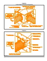
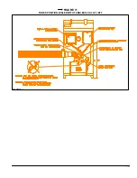
FIGURE 11 

TUBES POSITION BOILER WITH TANKLESS COIL AT LEFT


DNS-0689 Rev. C 

Содержание SCS-5-08-3

Страница 1: ...n Ne pas altérer votre unité ou ses contrôles Appeler un technicien qualifié Fabriqué par Division ICP UTC Canada Corporation 2003 10 06 X40015 Rév L SYSTÈME DE COMBUSTION SCELLÉE Modèles SCS 5 08 3 SCS 5 20 3 DNS 0474 Rév A 3400 boulevard Industriel Sherbrooke Québec J1L 1V8 ...

Страница 2: ...s l éventualité où il est impossible d obtenir cette température après 5 minutes de fonctionnement il est recommandé d utiliser une ou la combinaison des options suivantes a Re localiser l appareil de façon à raccourcir la longueur du tuyau d évacuation b Isoler le tuyau d évacuation en utilisant de l isolation FSK John Mansville ou l équivalent Enrouler l isolant autour du tuyau et le fixer avec ...

Страница 3: ...ce d Au dessus d un compteur de gaz ou d un régulateur ou à moins de 1 mètre 3 pieds du centre vertical du régulateur e À moins de 1 8 mètres 6 pieds de toute sortie d évent d un régulateur de gaz ou à moins de 1 mètre 3 pieds de l évent d un réservoir d huile ou de l entrée pour le remplissage de l huile f À moins de 0 3 mètre 1 pied au dessus du niveau du sol g À moins de 1 8 mètres 6 pieds de t...

Страница 4: ...itères de la partie 2 section 2 Une ouverture de 7 75 X 7 75 doit être effectuée pour l installation de la sortie d évacuation murale 2 4 2 Orientation des tuyaux flexibles L évacuateur mural est assemblé en usine et prêt à être utilisé selon deux configurations Si la configuration de l installation est la position 1 ou 4 montré à la figure 3 passer directement à la section 2 4 3 Si la configurati...

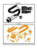
Страница 5: ...6 FIGURE 1 FIGURE 2 DNS 0701 Rév B DNS 0501 Rév D ...

Страница 6: ...7 VUE DE CÔTÉ FIGURE 3 DNS 0866 Rév A VUE ARRIÈRE ...

Страница 7: ... de Néoprène devrait sceller une surface ayant des irrégularités jusqu à Si nécessaire ajouter un scellant au silicone pour avoir un joint étanche 2 4 4 Installation des plaques pour conduits sur la sortie d évacuation murale Les prochaines étapes consistent à installer le tuyau d évacuation et d alimentation en air à l évacuateur mural tout en conservant l étanchéité de l assemblage Référer à la ...

Страница 8: ...s fournies en utilisant les languettes sur les plaques demi lunes 9 Fixer la plaque demi lune avec 4 vis pour sceller complètement le tuyau d alimentation en air sur l évacuateur mural 2 4 5 INSTALLATION DE LA BRIDE D ÉVACUATION DE L APPAREIL 1 Remplacer la bride d évacuation de 6 pouces de diamètre par la bride d évacuation de 5 pouces de diamètre fournie avec le système SCS voir figure 8 2 Coupe...

Страница 9: ...10 FIGURE 6 Installation droite du tuyau d évacuation 5 pouces de diamètre FIGURE 7 DNS 0481 Rév B DNS 0867 Rév A ...

Страница 10: ...2 8 BOÎTE DE CONTRÔLE DE SÉCURITÉ 1 La boîte électrique fournie avec cet appareil possède un interrupteur de pression et doit être installé verticalement pour respecter la calibration de l interrupteur de pression 2 La position proposée pour une installation pratique et un bon fonctionnement est montré à la figure 11 et à la figure 12 3 Insérer le tube identifié VACUUM dans le coin supérieur droit...

Страница 11: ...12 FIGURE 9 FIGURE 10 DNS 0468 Rév D ATTENTION CAUTION APPLIQUER UN JOINT DE SCELLANT APPLY A RED HIGH TEMPERATURE HAUTE TEMPÉRATURE SILICONE ROUGE SILICONE JOINT DNS 0887 Rév A ...

Страница 12: ...13 FIGURE 11 POSITIONNEMENT DES TUBES CHAUDIÈRE AVEC SERPENTIN À GAUCHE DNS 0689 Rév C ...

Страница 13: ...14 FIGURE 12 POSITIONNEMENT DES TUBES CHAUDIÈRE AVEC SERPENTIN À DROITE DNS 0690 Rév C ...

Страница 14: ... d ajustement d air de combustion 3 Tourner en sens horaire indication pour augmenter l air de combustion 4 Tourner en sens anti horaire indication pour diminuer l air de combustion 5 Réinstaller le bouchon en plastique sur le dessus du couvercle du brûleur une fois les ajustements terminés 3 1 3 Procédure pour test de fumée et CO2 1 Après un minimum de 5 à 10 minutes de fonctionnement et lorsque ...

Страница 15: ...vérifier la pression totale le vacuum et la pression référer à la figure 12 3 1 6 Fonctionnement anormal mode sécurité Lumière L 1 allumé Si l interrupteur PS 1 se ferme et que le contact TDR 1 est fermé après 4 secondes la bobine R 1 est alimentée Le contact CR 1 normalement fermé NC s ouvre coupant l alimentation électrique au brûleur Dans ce cas la lumière L 1 reste allumée pour indiquer que le...

Страница 16: ...17 FIGURE 13 Diagramme électrique DNS 0463 Rév C ...

Страница 17: ...18 FIGURE 14 Vérification de la pression totale de fonctionnement DNS 0499 Rév C ...

Страница 18: ...on Pour l entretien référer au manuel d installation de l appareil de chauffage L entretien d un système de combustion scellé est identique à l entretien d une cheminée mais avec la particularité suivante NETTOYAGE DE L APPAREIL Pour le service d entretien enlever la plaque d évacuation en dévissant les 8 écrous en laiton voir figure 8 Les collets n ont pas à être démontés sur l assemblage du tuya...

Страница 19: ...echnicien de service RÉSULTAT DU TEST DE MISE EN MARCHE Gicleur Pression lb po 2 Ajustements du brûleur Bande principale Bande fine Position de la tête CO2 Indice de fumée Bacharach Température des gaz à la sortie de l unité 0 F Température ambiante 0 F Tirage dans la cheminée W C Tirage au dessus du feu W C Examiné par ...

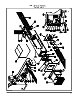
Страница 20: ...21 LISTE DE PIÈCES Modèle SCS 5 DNS 0475 Rév I ...

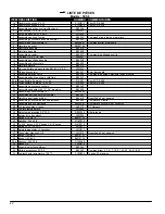
Страница 21: ...flexible 2 parois 4 X 11 AL Z13I007 Pour SCS 5 08 3 20b Tuyau flexible 2 parois 4 X 23 AL Z13I006 Pour SCS 5 20 3 21 Assemblage couvercle centrale B02045 22 Assemblage adapteur 90 o 3 X 4 diamètre B02049 23 Assemblage collet complet 4 B02048 03 24 Assemblage bride de brûleur complet B02041 25 Garniture de bride de brûleur B00419 Quantité de 2 par appareil 26 Assemblage couvercle de boîte électriqu...

Страница 22: ...future reference Caution Do not tamper with the unit or its controls Call a qualified service technician 2003 10 06 X40015 Rev L Models SCS 5 08 3 SCS 5 20 3 DNS 0474 Rev A Manufactured by Division ICP UTC Canada Corporation 3400 Industrial boulevard Sherbrooke Quebec J1L 1V8 ...

Страница 23: ...vent that you are not able to reach this temperature within 5 minutes from a cold start it is recommended that you increase it by using one or a combination of the following options a Relocate the furnace or boiler to shorten the flue pipe length b Insulate the vent pipe To do so use 1 inche of Microlite FSK insulation by John Mansville or an equivalent Wrap the insulation around the vent pipe and...

Страница 24: ...g d Above a gas meter regular assembly within 1 meter 3 feet horizontally of the vertical center line of the regulator e Within 1 8 meters 6 feet of any gas service regulator vent outlet or 1 meter 3 feet of an oil tank vent or oil tankfill inlet f Not less than 0 3 meter 1 foot above grade level g Within 1 8 meters 6 feet from another combustion appliance air intake h Within 1 8 meters 6 feet of ...

Страница 25: ...lexible connection The vent terminal is factory assembled with the vent pipe and is ready for use if your application calls for position 1 or position 4 as shown on figure 3 If the position required for the application is position 1 or 4 go directly to section 2 4 3 of this chapter If the position required for the application is one of 2 3 5 or 6 you should proceed using the following instructions...

Страница 26: ...6 FIGURE 1 FIGURE 2 DNS 0701 Rev B DNS 0501 Rev D ...

Страница 27: ...7 FIGURE 3 SIDE VIEW REAR VIEW DNS 0866 Rev A ...

Страница 28: ...4 Completion of the vent terminal assembly The next steps will be to secure the vent pipe and combustion air pipe to the vent terminal According to the installation position identified on figure 3 1 Chose the right position of the L shape end cover to accommodate the installation of the 5 inches diameter vent pipe on side or end connection as shown on figure 5 or figure 6 2 Use four metal screws t...

Страница 29: ...Replace the 6 inches diameter HMT Boiler breech plate with the 5 inches diameter breech plate supplied in the kit see figure 8 2 Cut the 5 inches flexible stainless steel vent pipe at the length needed 3 As illustrated on figure 7 insert the 5 inches flexible vent pipe to the smaller diameter of boiler breech Secure the pipe on breech with three metal screws at 3 8 from the end of vent pipe 4 Appl...

Страница 30: ...10 FIGURE 6 5 inches diameter Vent Pipe End Connection FIGURE 7 DNS 0481 Rev B DNS 0867 Rev A ...

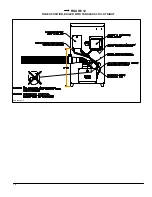
Страница 31: ...NS 1 The electric box supplied with this kit encloses pressure switch and should be installed vertically to respect the calibration of the pressure switch 2 The position for a practical installation and a proper operation is shown on the figure 11 and on the figure 12 3 Install the VACUUM silicone hose on the top right side 5 8 diameter opening of the Riello 40 BF5 Oil Burner with the compress fit...

Страница 32: ...12 FIGURE 9 FIGURE 10 DNS 0887 Rev A ATTENTION CAUTION APPLIQUER UN JOINT DE SCELLANT APPLY A RED HIGH TEMPERATURE HAUTE TEMPÉRATURE SILICONE ROUGE SILICONE JOINT DNS 0468 Rev D ...

Страница 33: ...13 FIGURE 11 TUBES POSITION BOILER WITH TANKLESS COIL AT LEFT DNS 0689 Rev C ...

Страница 34: ...14 FIGURE 12 TUBES POSITION BOILER WITH TANKLESS COIL AT RIGHT DNS 0690 Rev C ...

Страница 35: ...ir shutter adjustment screw 3 Turning the screw clockwise indicator to increase combustion air 4 Turning the screw anti clockwise indicator to decrease combustion air 5 Installing back the plastic plug when the air shutter adjustment is completed 3 1 3 Perform the smoke and CO2 test 1 Start the appliance and from the test port provided on the BREECH PLATE of the boiler proceed with smoke test and ...

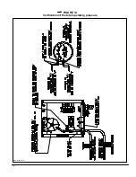
Страница 36: ...ration of the heating unit For total pressure testing pressure and vacuum testing refer to figure 14 3 1 6 Abnormal operation Lock out indicator light L 1 is ON If the PS 1 contact closes and the TDR 1 contact is closed after 4 seconds the electric power is applied on the R 1 coil The CR 1 normally closed contact opens and the burner shuts down In this case the lock out indicator light stays open ...

Страница 37: ...17 FIGURE 13 Electric wiring diagram DNS 0643 Rev C ...

Страница 38: ...18 FIGURE 14 Verification of the total operating pressure DNS 0499 Rév C ...

Страница 39: ...es refer to the instruction manual of the appliance The maintenance of a sealed combustion system is the same of the maintenance of an appliance using a chimney but with the following particularity CLEANING OF THE UNIT Remove breech plate and vent pipe assembly from the boiler smoke box as showed on figure 8 The collars must not be remove from the vent pipe assembly ...

Страница 40: ...ervice telephones day Night Dealer s name and address RESULT OF START UP TEST Nozzle Pressure Lbpsi Burner adjustments Primary air Fine air Draw Assembly CO2 Smoke scale Bacharach Gross stack temperature 0 F Ambiant temperature 0 F Chimney draft C E Overfire draft C E Test made by ...

Страница 41: ...21 PARTS LIST Model SCS 5 DNS 0475 Rev I ...

Страница 42: ...r SCS 5 08 3 20b Flexible pipe 2 walls 4 X 23 AL Z13I006 For SCS 5 20 3 21 Central cover ass y B02045 22 Adaptor 90 o 3 X 4 diameter ass y B02049 23 Complete 4 collar ass y B02048 03 24 Complete burner flange ass y B02041 25 Burner flange gasket B00419 Quantity of 2 per appliance 26 Electrical box cover ass y B02044 Complete with label 27 Electrical box ass y B02039 01 Complete with cover and cont...

Отзывы: