15
PART 3
OPERATION
3.1)
START-UP AND ADJUSTMENTS
For the start-up of your heating unit, please refer to the
instruction manual that came with it. Using a SCS
System is similar to a conventional chimney with the
following particularities.
CAUTION
This procedure should be done only by a
qualified technician.
3.1.1) OIL BURNER SPECIFICATIONS
The SCS system is certified for the RIELLO 40-BF5 oil
burner for an input range of 1.00 to 1.35 USGPH.
Refer to table 2 for operation specifications. For oil
burner servicing refer to the oil burner instruction
manual.
The 40-BF5 Oil Burner used with the SCS
System should never operate without the outdoor
combustion air provision.
3.1.2) Setting the 40-BF5 burner air
damper adjustment
Note:
Variations in flue gas smoke and CO
2
readings
will occur with the burner cover in place or not
in place. Therefore, the burner cover must be
in place when making the final combustion
instrument readings to ensure proper test
results.
The 40-BF5 air shutter adjustments can be made with
the burner cover in place by :
1. Removing the plastic plug on the top of the
burner cover;
2. Using a Phillips screwdriver you could reach the
air shutter adjustment screw;
3. Turning the screw clockwise ( + indicator) to
increase combustion air;
4. Turning the screw anti-clockwise( - indicator) to
decrease combustion air;
5. Installing back the plastic plug when the air
shutter adjustment is completed.
3.1.3) Perform the smoke and CO
2
test
1. Start the appliance and from the test port
provided on the BREECH PLATE of the boiler,
proceed with smoke test and adjust the burner to
get between #1 and a "trace" of smoke rating
after at least 5 to 10 minutes of operation and
also with a minimum of 140
o
F (60
o
C) water
temperature;
2. Measure the CO
2
(or O
2
) and note it. This is the
vital reference point for further adjustments;
Example : 13.5 % CO
2
(or 2.6 % O
2
)
3. Open the burner air damper to get 0.5 to 1.5%
CO
2
less than the previous reading (0.7 to 2.0 %
of O
2
more then the previous reading);
Example : Reduce CO
2
from 13.5 to 12.5 % (or
increase O
2
from 2.6 to 4.2 %)
4. Take a smoke test in this condition. The new
smoke reading should give you between a "trace"
and #0.
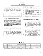
TABLE 2
Capacity
Input
Burner
Nozzle
*Turbulator
*Air
Pump Press.
(BTU / H)
(USGPH)
Model
Delavan
Danfoss
Setting
Band
(PSI)
118 000
1.00
Riello 40-BF5
0.85-80B
0.85-80AS
1
4
140
141 000
1.2
Riello 40-BF5
1.10-80B
1.10-80AS
1
6
120
158 000
1.35
Riello 40-BF5
1.10-80B
1.10-80AS
2
4
150
* Air adjustment setting with the burner cover installed. Can change from one unit to another.
Содержание SCS-5-08-3
Страница 5: ...6 FIGURE 1 FIGURE 2 DNS 0701 Rév B DNS 0501 Rév D ...
Страница 6: ...7 VUE DE CÔTÉ FIGURE 3 DNS 0866 Rév A VUE ARRIÈRE ...
Страница 12: ...13 FIGURE 11 POSITIONNEMENT DES TUBES CHAUDIÈRE AVEC SERPENTIN À GAUCHE DNS 0689 Rév C ...
Страница 13: ...14 FIGURE 12 POSITIONNEMENT DES TUBES CHAUDIÈRE AVEC SERPENTIN À DROITE DNS 0690 Rév C ...
Страница 16: ...17 FIGURE 13 Diagramme électrique DNS 0463 Rév C ...
Страница 17: ...18 FIGURE 14 Vérification de la pression totale de fonctionnement DNS 0499 Rév C ...
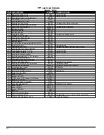
Страница 20: ...21 LISTE DE PIÈCES Modèle SCS 5 DNS 0475 Rév I ...
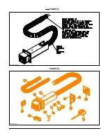
Страница 26: ...6 FIGURE 1 FIGURE 2 DNS 0701 Rev B DNS 0501 Rev D ...
Страница 27: ...7 FIGURE 3 SIDE VIEW REAR VIEW DNS 0866 Rev A ...
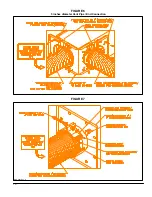
Страница 30: ...10 FIGURE 6 5 inches diameter Vent Pipe End Connection FIGURE 7 DNS 0481 Rev B DNS 0867 Rev A ...
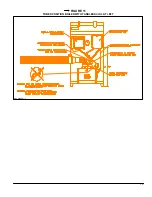
Страница 33: ...13 FIGURE 11 TUBES POSITION BOILER WITH TANKLESS COIL AT LEFT DNS 0689 Rev C ...
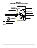
Страница 34: ...14 FIGURE 12 TUBES POSITION BOILER WITH TANKLESS COIL AT RIGHT DNS 0690 Rev C ...
Страница 37: ...17 FIGURE 13 Electric wiring diagram DNS 0643 Rev C ...
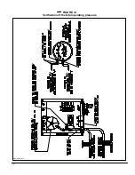
Страница 38: ...18 FIGURE 14 Verification of the total operating pressure DNS 0499 Rév C ...
Страница 41: ...21 PARTS LIST Model SCS 5 DNS 0475 Rev I ...

