background image

USSC

2

NOTE: DIAGRAMS & ILLUSTRATIONS NOT TO SCALE

Introduction...............................................2

Important Information................................2

Gas Specifications....................................2

Furnace Dimensions.................................3

Planning your Furnace Installation........4-5

Installation Instructions for Optional

Blower Kit.........................................5

Operation and Maintenance.................6-7

Venting Instructions..............................7-8

Venting Tables..........................................9

Pipe Installation.................................10-12

Gas Pressure Requirements.................13

Millivolt System Check...........................13

Testing Manifold & Inlet Pressure..........14

LP/Natural Gas Conversion...................14

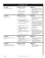
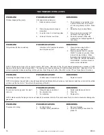
Troubleshooting................................15-16

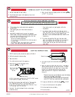
Lighting Instruction Label.......................17

Repair Parts (Generator Assembly).18-19

Repair Parts (Main Assembly)..........20-21

Optional Kits...........................................22

Wiring Diagrams...............................23-25

Notes................................................26-27

How To Order Repair Parts...................28

WARNING:  Do not operate appliance with the
glass door removed, cracked or broken. Re-
placement of the glass should be done by a
licensed or qualified service person.

CAUTION:  Label all wires prior to disconnec-
tion when servicing controls.  Wiring errors can
cause improper and dangerous operation.
Verify proper operation after servicing.

5.

This appliance gives off high

temperatures and should be located out of
heavy traffic areas and away from furniture
and draperies.

6.

Children and adults should be alerted

to the hazards of the high surface
temperatures of this appliance and should
stay away to avoid burns or ignition of
clothing.

7.

Children should be carefully

supervised when they are in the same room
as the fireplace.

8.

Under no circumstances should this

appliance be modified.  Do not operate this
appliance if any parts have been removed
for service.

9.

Installation and any repairs to this

appliance should be done by a qualified
service person.  A professional service
person should be called to inspect this
appliance annually.  Make it a practice to
have all of your gas appliances checked
annually.

10. Control compartments, burners and air
passages in this appliance should be kept
clean and free of dust and lint.  Make sure
that the gas valve and pilot light are turned
off before you attempt to clean this unit.

11. The appliance's venting system should
be inspected at least once a year and
immediately cleaned if necessary.

12. Keep the area around the appliance
clear of combustible materials, gasoline
and other flammable vapors and liquids.
Do not use this appliance as a drying rack
for clothing, nor should Christmas stockings
or decorations be hung in its immediate
area.

13. Do not operate this appliance without
glass in place.  Replace damaged glass
only with equivalent glass of equal
thickness and size (available from your
dealer).

14. Never burn solid fuel (wood, paper,
cardboard, coal) in this appliance.

15. Do not use this appliance if any part
has been under water.  Immediately call a
qualified service technician to inspect the
heater and to replace any part of the control
system and any gas control which has been
under water.

16.  The glass must be replaced in the door,
(if removed for service) before operating
the appliance.

For safe installation and operation of your
fireplace, please note the following:

1.

This appliance should only be installed

by a qualified installer.  Installation must
conform with local codes, or in the absence
of local codes, with the latest edition of the
National Fuel Gas Code, ANSI Z 223.1-
1992/NFPA 54-1992.

2.  A manufactured home (mobile home)
installation must conform with the
Manufactured Home Construction and
Safety Standard, Title 24 CFR, Part 3280,
or, when such a standard is not applicable,
the Standard for Manufactured Home
Installations, ANSI A225.1/NFPA 501A.

3.

Clothing or other flammable material

should not be placed on or near the
appliance.

4.

The flow of combustion and ventilation

air must not be obstructed.

IMPORTANT INFORMATION

Thank you for your purchase of the Model
9660 Gravity type vented wall furnace.  By
following the instructions in this manual
you can be assured of an installation that
will add both beauty and value to your
home, as well as provide safe, efficient
supplemental heat.

Your dealer can be a valuable source of
information as well as recommending pro-
fessionals who can assist in installation
and maintenance.

Improper maintenance may void war-
ranty and can cause injury or property
damage. Refer to this manual.

INTRODUCTION

TABLE OF CONTENTS

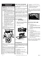
GAS SPECIFICATIONS

GAS

MAXIMUM

MODEL

FUEL

CONTROL

INPUT

9660N

Natural

Remote On/Off

24,000 BTU/HR

9660L

Propane/LP

Remote On/Off

20,000 BTU/HR

Manifold Pressure - Natural Gas 3.5" water column pressure
                                Propane/LP Gas 10" water column pressure

Gas Inlet - 3/8" NPT

SUPPLY

MINIMUM PRESSURE*

MAXIMUM PRESSURE

NATURAL GAS

5" W.C.P.

10.5" W.C.P.

PROPANE/LP GAS

11.0" W.C.P.

13.0" W.C.P.


    *For the purpose of Input Adjustment.

Содержание 9660

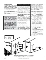
Страница 1: ...on may result causing property damage personal injury or loss of life Do not store or use gasoline or other flammable vapors and liquids in the vicinity of this or any other appliance WHAT TO DO IF YOU SMELL GAS Do not try to light any appliance Do not touch any electrical switch do not use any phone in your building Immediately call your gas supplier from a neighbor s phone Follow the gas supplie...

Страница 2: ...and liquids Do not use this appliance as a drying rack for clothing nor should Christmas stockings or decorations be hung in its immediate area 13 Do not operate this appliance without glass in place Replace damaged glass only with equivalent glass of equal thickness and size available from your dealer 14 Never burn solid fuel wood paper cardboard coal in this appliance 15 Do not use this applianc...

Страница 3: ...O SCALE GAS FURNACE DIMENSIONS TOP VIEW FRONT VIEW SIDE VIEW 27 3 8 28 1 4 9 3 4 10 1 2 18 11 16 23 5 8 34 1 8 34 7 8 3 1 2 32 3 4 37 9 16 37 9 16 15 11 16 16 1 4 35 15 16 8 5 16 5 1 2 15 11 16 TOP VIEW SHOWN WITHOUT FURNACE TRIM FOR CLARITY ...

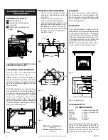
Страница 4: ...tant paint or finish on the mantel to prevent discoloration Fig 3 Fig 4a Fig 5 34 1 8 37 3 8 15 11 16 11 1 2 12 37 3 8 12 37 3 8 15 11 16 16 o c 11 1 2 23 5 8 57 1 16 40 3 8 28 9 16 12 7 8 Fig 4b Minimum wall thickness 4 inches Maximum wall thickness 6 inches 10 8 6 4 2 18 16 14 12 10 WALL TOP OF GRILL OPENING Fig 6 Mantel Chart CLEARANCE TO COMBUSTIBLES BACK 0 inches from standoffs SIDES 0 inches...

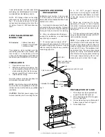
Страница 5: ...ve during any pressure testing of the gas supply piping system at test pressure equal to or less than 1 2 psig UNIT SIDE SEAL THIS AREA WITH HIGH TEMP CAULK PIPE COUPLING PIPE MANUAL SHUTOFF VALVE TEE JOINT PIPE NIPPLE CAP SEDIMENT TRAP Fig 7 INSTALLATION OF LOGS 1 Place large rear logs against back support bracket flat spots up 2 Place front log against front support bracket flat spots 3 Place sm...

Страница 6: ...flame control DO NOT ALTER GAS ORIFICE Unless converting from LP to Natural or Vice Versa 4 Periodic visual checks of the Pilot Flame should be conducted to ensure that the flame is continuously present except when the valve knob is in the OFF position 1 To turn off the Main Burner only use Main Burner switch or turn Valve Knob to PILOT position SHUT DOWN PROCEDURE PILOT O F F PILOT O N Sit E A TP...

Страница 7: ...660 furnace is designed for direct venting through a side wall or roof Only venting components specifically approved and labeled for this furnace may be used The flow of combustion and ventilation air must not be obstructed Minimum clearance between vent pipes and combustible materials is one 1 inch CAUTION ALL JOINTS MUST BE AIR TIGHT THE INSTALLATION OF THIS APPLIANCE MUST CONFORM WITH LOCAL COD...

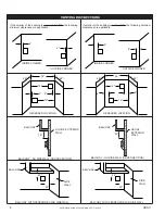
Страница 8: ...minimum clearances are applicable 2 2 12 12 48 48 24 12 12 36 48 48 6 6 2 2 6 6 INSIDE CORNER OUTSIDE CORNER INSIDE CORNER OUTSIDE CORNER RECESSED LOCATION RECESSED LOCATION BALCONY HOUSE EXTERIOR WALL BALCONY NO SIDE WALL CROSS SECTION BALCONY WITH PERPENDICULAR SIDE WALL BALCONY WITH PERPENDICULAR SIDE WALL 24 20 BALCONY NO SIDE WALL CROSS SECTION HOUSE EXTERIOR WALL BALCONY 24 18 SIDE WALL BALC...

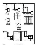
Страница 9: ...10 35 6 8 12 34 7 8 14 33 8 8 16 32 9 8 16 31 V V V 40 Max H 8 Max 1 1 1 T TABLE E H 12 Min H 24 Max TABLE F V H H H Min Max Max 1 2 2 2 4 4 3 6 6 4 8 8 5 8 10 6 8 12 7 8 14 8 8 16 9 8 16 V 20 Max H 8 Max H H H 16 Max 1 T 1 H TABLE D TABLE D H 12 Min H 24 Max TABLE B V H Min Max 1 2 2 4 3 6 4 8 5 8 V 40 Max H 8 Max T T H TABLE E TOP VIEW H H1 V HT TABLE F 1 H H1 V HT TABLE F 2 variation with 3 elb...

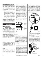
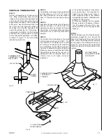
Страница 10: ...heVent Termination to the exterior wall run a bead of non hardening mastic around it s outside edges so as to make a seal between it and the wall The arrow on the vent cap should be pointing up Insure that proper clearances to combustible materials are maintained Figure 14 1 The horizontal run of vent must have a 1 4 inch rise for every 1 foot of run towards the termination Never allow the vent to...

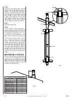
Страница 11: ...ked position STEP 4 Cut a hole in the roof centered on the small drill hole placed in the roof in STEP 1 The hole should be of sufficient size to meet the minimum requirements for clearance to combustibles as specified on page 8 Continue to assemble lengths of Pipe and Elbows necessary to reach from the Ceiling Support Box up through the roof line A galvanized finish is desirable above the rooflin...

Страница 12: ...e first floor including closets and storage spaces which the vertical vent passes through must be enclosed The enclosure may be framed and sheetrocked with stan dard construction materials see page 8 for minimum allowable clearance between the outside of the vent pipe and the com bustible surfaces of the enclosure Do not fill any of the required air spaces with in sulation IMPORTANT NOTICE If for ...

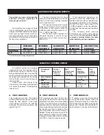
Страница 13: ...xceed the length recommended in the Wiring Section Table and all connections are clean and tight Conduct each check shown in the chart below by connecting meter test leads to terminals as indicated All readings are closed circuit Component Connect Wall Meter See Check Meter Test Thermostat Reading Check Leads To Contacts Should Be Results Terminals Should Be Below Valve Operator Greater Than Syste...

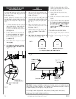
Страница 14: ... the base of the pilot and tighten nut 5 Next locate the conversion cap on the control and remove it Fig 22 6 Rotate the conversion cap until the desired gas designation is exposed and reinstall it in the control 7 Open glass door and remove the ceramic logs 8 Remove burner screw and then remove burner 9 Unscrew burner orifice and install orifice for the gas to be used as identified on the unit ra...

Страница 15: ...o to spill switch wire 5 Thermopile is defective dirty or 5 Test with millivolt meter and replace weak if necessary 6 Thermopile is shorting out where it 6 Replace thermopile passes through cabinet 7 Gas valve will not prove pilot 7 Replace valve 8 Air in line 8 Purge air from gas line 9 Wire from valve to wall switch or 9 Remove wall switch wires from top remote switch is nicked or shorting and b...

Страница 16: ... excess of 1 200 degrees Fahrenheit constant temperature The window only reaches between 500 600 degrees Fahrenheit Because of this it is almost impossible to bake something into the window Most things will with a little effort some off if you follow these directions Circulating fan speed does not vary Variable speed rheostat defective Replace rheostat NOTE Only replace rheostat with a rheostat su...

Страница 17: ...these instructions exactly a fire or explosion may result causing property damage personal injury or loss of life PILOT O F F PILOT O N Sit E A TP TH TP TH LIGHTING INSTRUCTIONS 1 STOP Read the safety information above on this label 2 Set the thermostat to lowest setting 3 Open lower door 4 Turn off all electric power to the appliance 5 Push in gas control knob slightly and turn clockwise to OFF N...

Страница 18: ...USSC 18 NOTE DIAGRAMS ILLUSTRATIONS NOT TO SCALE MODEL 9660 GENERATOR REPAIR PARTS 19 20 21 22 1 16 17 3 2 18 12 10 11 13 14 9 7 5 15 4 6 8 ...

Страница 19: ... Control Bracket 24241 1 11 Piezo Bracket w Screw 89760 1 12 Piezo w Nut 89761 1 13 Sit Control 81182 1 14 16ga Link Chain 86318 1 FT 15 Thermopile C43815 1 16 Sit Thermo Couple 89759 1 17 L P Sit Pilot 89757 1 Natural Gas Sit Pilot 89758 1 18 Generator Gasket 88086 1 8 x 1 2 Teks 83437 8 Piezo Cable 80375 1 Wire Assembly 80376 1 10 32 x 3 8 Machine Screw 83464 4 19 Top Fork Log 89771 1 20 Top Twi...

Страница 20: ...USSC 20 NOTE DIAGRAMS ILLUSTRATIONS NOT TO SCALE MODEL 9660 GAS FURNACE REPAIR PARTS 1 3 5 6 7 8 9 10 11 12 13 14 15 16 17 18 19 20 21 23 4 24 25 22 26 27 31 30 29 28 2 7 ...

Страница 21: ... Grill Hinge C18513 2 12 Firebox Bottom 24259 1 13 Firebox Divider 24250 1 Flue Outlet 89754 1 14 Firebox Wrapper 24253 1 Starting Collar 89756 1 15 Firebox Shield 24265 1 16 Firebox Top 24258 1 17 Latch w Keeper 89755 2 18 Insulation 24266 1 19 Firebox Front 24251 1 20 Inner Baffle 24279 1 21 Baffle Plate 24252 1 22 Vent Termination Assembly 68997 1 23 12 CO AX Pipe 89765 1 24 Insulation Shield 2...

Страница 22: ... BRASS DOOR TRIM KIT MODEL RCK60 REMOTE CONTROL KIT REMOTE SKYTECH SKYTECH 1001 ON OFF INDICATOR R E M O T E NO OFF SKYTECH MODEL WSK60 WALL SWITCH KIT MODEL WTK60 WALL THERMOSTAT KIT 50 60 70 80 90 21 10 32 c 50 60 70 80 90 21 10 32 c MODEL FVK60 FULL VIEW DOOR KIT MODEL CBK60 REFRACTORY CERAMIC BRICK KIT ...

Страница 23: ...R GENERATOR ASSEMBLY WHITE Neutral BLACK Hot GREEN Ground 2x4 BOX GREEN BLACK BLACK ATTACH GROUND TO SIDE OF UNIT WITH SCREW INCLUDED THERMO DISC 1 4 FEMALE INS 1 4 MALE INS 1 4 FEMALE INS BLOWER RHEOSTAT 1 4 MALE INS 1 4 MALE INS WHITE WHITE 80378 80378 80377 80377 CONTROL WIRING TERMINALS THERMOPILE ROCKER SWITCH ...

Страница 24: ...kits can be used at a time Example If you have the Optional Remote Control Kit and the Optional Wall Switch Kit operation of the unit must be controlled by one or the other If you want to use the remote control simply turn the Wall Switch to OFF STANDARD WIRING FROM FACTORY WIRING OF THE RCK60 REMOTE CONTROL KIT WIRING WITH THE WTK60 WALL THERMOSTAT KIT PILOT O F F PILOT O N Sit E A TP TH TP TH RO...

Страница 25: ...time Example If you want to control the operation of this unit with the Remote Control then you must turn the Wall Switch OFF When trying to use two Optional kits at once one will always override the other PILOT O F F PILOT O N Sit E A TP TH TP TH ROCKER SWITCH CONTROL VALVE REMOTE CONTROL SENSOR PIGGYBACK DISCONNECT 50 60 70 80 90 21 10 32 c 50 60 70 80 90 21 10 32 c WALL THERMOSTAT Note When com...

Страница 26: ...USSC 26 NOTE DIAGRAMS ILLUSTRATIONS NOT TO SCALE NOTES ...

Страница 27: ...USSC 27 NOTE DIAGRAMS ILLUSTRATIONS NOT TO SCALE NOTES ...

Страница 28: ...RENCE WHEN WRITING ALWAYS GIVE THE FULL MODEL NUMBER WHICH IS ON THE NAMEPLATE ATTACHED TO THE HEATER WHEN ORDERING REPAIR PARTS ALWAYS GIVE THE FOLLOWING INFORMATION AS SHOWN IN THIS LIST 1 THE PART NUMBER 2 THE PART DESCRIPTION 3 THE MODEL NUMBER 9660 4 THE SERIAL NUMBER ____________________ UNITED STATES STOVE COMPANY 227 INDUSTRIAL PARK ROAD PO BOX 151 SOUTH PITTSBURG TN 37380 423 837 2100 DES...

Отзывы: