14
E N G L I S H
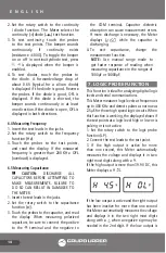
2. Set the rotary switch to the continuity
/ diode function. The Meter selects the
continuity ( )diode (
) test function.
3. To test continuity, touch the probes
to the test points. The beeper sounds
continuously if continuity exists
(resistance <100Ω). To toggle the beeper
on or off in continuity/diode test, press
. is displayed when the beeper is
enabled.
4. To test diodes, touch the probes to
the diode. A forwardvoltage drop of
about 0.6V (typical for a silicon diode)
is displayed if the diode is good. Reverse
the probes. If the diode is good, OFL is
displayed. If the diode is shorted, the
beeper sounds continuously in at least
one direction.If the diode is open, OFL is
displayed in both directions.
6.4 Measuring Frequency
1. Insert the test leads in the jacks.
2. Set the rotary switch to the frequency
function (Hz).
3. Touch the probes to the test points,
and read the display. If the measured
frequency is greater than 200 KHz. OFL
(overload) is displayed.
6.5 Measuring Capacitance
CAUTION: DISCHARGE ALL
CAPACITORS BEFORE ATTEMPTING TO
MAKE MEASUREMENTS. FAILURE TO
DO SO CAN RESLUT IN DAMAGES TO
THE METER.
1. Insert the test leads in the jacks.
2. Set the rotary switch to the capacitance
function ( ).
3. Touch the probes to the capacitor, and read
the display. When measuring polarized
capacitors, be sure to connect the positive
to the terminal and the negative to
the COM terminal. Capacitor dielectric
absorption can cause measurement errors.
If more discharge is necessary, the Meter
displays (
) while the capacitor is
discharging.
4. To exit capacitance, change the
measurement function.
NOTE: Use manual range mode to
get faster response of reading when
measuring capacitance in the ranges of
1000μF or 10000μF.
7. LOGIC PROBE FUNCTION
This Function is ideal for analyzing digital logic
levels and serial communications.
This Meter measures logic levels at frequencies
up to 400 KHz and detects pulses as narrow as
2.5μS for those high speed logic circuits. When
this function is working, the displayed shows if
the test points at a logic level high or low or is
pulsing or is not active.
1. Set the rotary switch to the logic probe
function (LP).
2. Connect the test leads to the test point.
3. If the high output is active for more
than one second, this Meter automatically
measures the voltage and displays it in two
right most digits along with a .
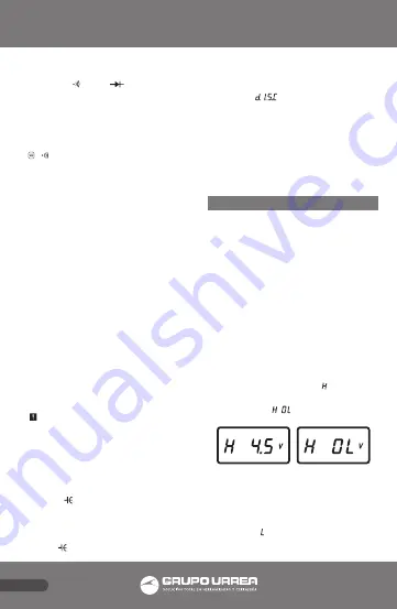
If the high output is more than 39.9 V DC, this
Meter displays a .
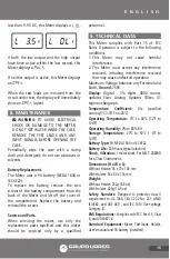
If the low output is active and the right output
has been inactive for more than one second
this Meter automatically measures the voltage
and displays it in the two right most digits
along with a , when a negative sign may be
needed in the 2nd digit. If the low output is
Содержание UD18
Страница 18: ...18 NOTAS NOTES...
Страница 19: ...19 NOTAS NOTES...


