


sec.3g
−−−−
17
2 VOICE - Technical Manual
ELEKTA AND ELEKTA STEEL CALL MODULE
2VOICE ELEKTA CALL MODULE Ref. 1083/15 (50Hz) – 1083/25 (60Hz)
2VOICE ELEKTA STEEL CALL MODULE Ref. 1083/16 (50Hz) – 1083/27 (60Hz)
ANNEX
ANNEX
PROGRAMMING AND USE OF THE SIMPLIFIED
GUI
Simpli
fi
ed GUI is used to select to use a very simple user interface
(GUI) allowing the user to select one or more columns (or blocks) in
the system and enter the number of the apartment to be called.
To enter the programming procedure, see paragraph “Access to
Programming Procedure”.
To change the language of the calling module, see paragraph
“Language”.
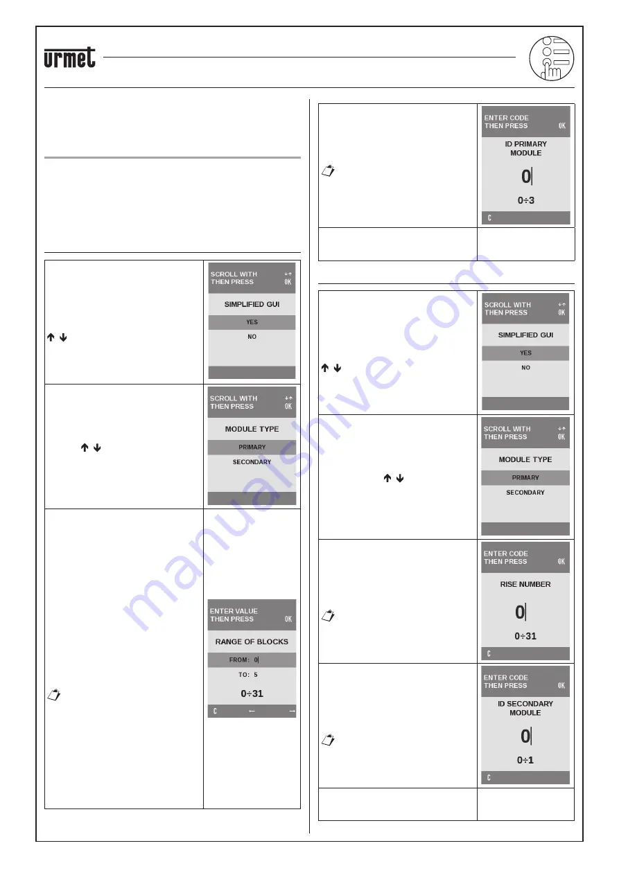
CONFIGURATION OF PRIMARY CALL MODULE
Select CONFIGURATION on the main
menu. The menu shown to the side
appears where the user can press the
, to select
YES
.
Then select the type of PRIMARY module
with the
buttons and press
OK
to
con
fi
rm.
The following screen appears and it is
used to de
fi
ne which columns (or blocks)
may be called from the calling module.
Ranges which include only some of
the blocks present in the system may
be de
fi
ned (e.g. FROM:3 TO: 12). After
having inserted a range of blocks, a
default name will be assigned to each
block, e.g. BLOCK X, where X means A
for the
fi
rst block (the one with column 0
addresses), B the second block (column
1 addresses) and so on to block 25.
Blocks from 26 to 31 will be identi
fi
ed
by letters ZA ÷ ZF. The default names
can be customized in the second level
BLOCKS menu described below. The
following screenshot shows an example
of con
fi
guration for calling six blocks.
If the user wants to call a single
block from the PRIMARY calling
module, the BLOCKS INTERVAL
must be con
fi
gured as follows:
FROM: X
TO: X
Where X is the number of the block to
be called.
The default value of the interval is
FROM: 0
TO: 0
Set the identi
fi
cation code (ID) of the
primary module on the keypad and press
OK
to con
fi
rm the selection.
Admissible values: 0÷3
An error will appear when
exiting con
fi
guration mode
and returning the device to
normal operating mode if a
previously used ID is set.
The next items on the menu are the same
as shown in the table, where on the
bottom right, there is (*Annex)
CONFIGURATION OF SECONDARY CALL MODULE
Select CONFIGURATION on the main
menu. The menu shown to the side
appears where the user can press the
, to select
YES
.
Then select the type of SECONDARY
module with the
buttons and press
OK
to con
fi
rm.
Set the column number of the secondary
module on the keypad and press OK to
con
fi
rm the selection.
Permitted values: 0 ÷ 31
No speci
fi
c error is indicated if
an incorrect column number is
set but no user can be called.
Each column may have up to two
secondary modules. Set the identi
fi
cation
code (ID) of the secondary module in the
riser on the keypad and press
OK
to
con
fi
rm the selection.
Permitted values: 0 or 1.
Secondary module ID errors
will only be shown when
exiting con
fi
guration mode and
returning the device to normal
operating mode.
The next items on the menu are the same
as shown in the table, where on the
bottom right, there is (*Annex).


