


11
DS1060-148
6. DEVICE CONFIGURATION
Refer to the system technical manual in the Manuals area for con
fi
guration of the device.
Technical Manuals / Communication / Ipercom System at
www.urmet.com
.
You are advised to remove the QR code label from the front of the device and place it on the front
panel
fi
lm so that the QR code can be scanned during con
fi
guration.
7. HOW TO REBOOT/RESET DEFAULT SETTINGS
Press the RESET button (10) once for a short time to reboot the device. LEDs (1) will
fl
ash once to con
fi
rm
the operation.
Quickly press the RESET button (10)
fi
ve consecutive times (less than 1 second apart) to restore to default
settings and cancel all con
fi
gurations made. LEDs (1) will
fl
ash 5 times to con
fi
rm the operation.
8. SPEAKER VOLUME ADJUSTMENT
Volumes are calibrated by default so not to require adjustments in most cases.
Use a screwdriver to adjust the speaker volume (15), if required.
9. DDA (Disability Discrimination Act) LED ACTUATION
- SYSTEM STATUS INDICATION
The system state is shown by the following indications which appear on the door unit front:
a) call in progress: LED
on green and voice message “CALL IN PROGRESS”
b) line engaged: LED
on red and voice message “THE LINE IS BUSY”
c) off-hook waiting time expired: voice message “THE USER IS NOT ANSWERING”;
d) conversion in progress: LED
on orange;
e) conversation paused by the switchboard: LED
on green and LED
fl
ashing orange.
f) door open: LED green and “THE DOOR IS OPEN” voice message.
10. PEDESTRIAN LOCK ACTUATION
The door unit has two terminals for managing the pedestrian door lock (SE+ and SE-). The electric lock is
operated in the following cases:
whenever the hall button is pressed (terminals PA, CT);
when a door open command is received from an apartment station according to the con
fi
guration
(“free” or “privacy”).
11. GARAGE GATE LOCK ACTUATION
The audio and audio-video door units have two terminals (SE2) connected to the contacts of a normally
open relay which can be used to control a gate opening control unit (*). The relay is operated for 1 second
after receiving the garage door opening command according to the operating mode (“free” or “privacy”) as
the door lock.
(*)
The relay is NOT suitable to control direct power loads and can only be used as control relay.
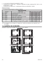
12. INSTALLATION CONSTRAINTS
Some installation constraints must be respected for installing the panel. The following are allowed for each
con
fi
guration:
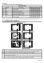
Panel with button modules
A total maximum number of 12 installed modules;
One IP audio video door unit module ref. 1060/48;
A single ILA and voice synthesis module Ref. 1168/48;
A single proximity key reader module Ref. 1168/45;
Maximum insertion of 11 four-button expansion modules Ref. 1168/4 or eight-button modules Ref.
1168/8;
Maximum insertion of 11 door number modules Ref. 1168/50
•
•
•
•
•
•
•
•


