


2. Safety Devices
■
Safety Device Information
For emer gency op er a tion con trols and pro ce dures
see the Emer gency Op er a tion chap ter 9, in this
manual.
The de vices listed in this chap ter are safety de -
vices.
They are on an
RT
to in crease safety in the work
place for both the op er a tor and other peo ple near
the ma chine.
Do not by-pass, disable, modify, or ignore
any of these devices. Check them carefully
at the start of each work shift to see that they
are in working order (see Daily Inspection &
Maintenance chapter 7). If any is found to be
defective, remove the
RT
from service
immediately until a qualified service
technician can make repairs.
■
Emergency Stop Switches
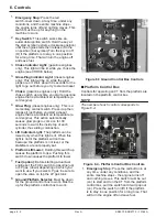
❑
At platform control box
Figure 2.1 - Platform Control Box Emergency
Stop Switch
Press the large red
EMERGENCY STOP
but ton in
and the en tire ma chine stops, the en gine turns off,
and noth ing moves. This switch must be out (on) to
con trol the
RT
from the plat form (pull the switch
and it will pop out).
❑
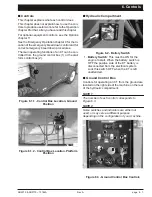
At ground control box
Figure 2.2 - Ground Control Box Emergency
Stop Switch
Press the red
EMERGENCY STOP
switch cover
down, at any time, un der any con di tions, and the
en
tire ma
chine stops, the en
gine turns off, and
noth ing moves. the EMERGENCY STOP switch
must be up for any thing on the
RT
to work.
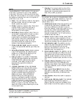
■
Alarms
There are two alarms on an
RT
. One is lo cated in
the plat form con trol box, the other is lo cated in the
ground con trol box.
The alarms are con nected in par al lel, they both
emit the same pat tern of sound at the same time.
The dif fer ent alarm sound pat terns are shown in
the ta ble im me di ately be low and dis cussed be low
the table.
Figure 2.3 - Alarm Sound Patterns
The high-tem per a ture, low oil-pres sure, and al ter -
na tor not-charg ing alarms are each a con tin u ous
tone.
SR3370 & SR2770 – 13184A
Rev A
page 2 - 1
WARNING


