Maintenance
Section
4-22
AB38 Work Platform
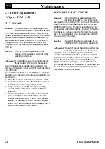
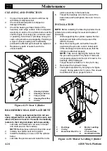
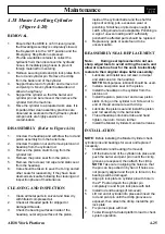
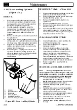
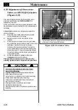
4.16 Telescopic Cylinder
(Figure 4-18)
REMOVAL
1.
Ensure that the AB38 is on firm level ground,
the Elevating Assembly is completely stowed,
the Keyswitch is to the ‘OFF’ position and the
Emergency Stop Button is pressed.
2.
From Chassis Controls extend the Telescope
until the Rod End Pin is just visible. This will
leave a small amount of clearance between the
ground and the Telescopic Boom.
3.
Support the Telescopic Boom & Platform
Assembly to avoid any damage while removing
the Telescopic Cylinder.
4.
Provide a suitable container to collect the
hydraulic fluid, then disconnect the hydraulic
hoses. Immediately plug hoses to prevent
foreign material from entering.
5.
Remove securing bolts and pin lock plates from
the barrel end cylinder pin.
6.
Remove the Telescopic Cylinder rod end circlip
and then push the rod end pin out.
7.
Support the cylinder so that the barrel end
cylinder pin can be removed, then remove the
cylinder from the machine. This is done by
pulling the cylinder forward through the gap
provided in Boom 2 at the 2
nd
post end.
8.
Move the cylinder to a prepared work area. It is
important that clean assembly practices are
observed. Seals and other cylinder components
are highly sensitive to contamination.
DISASSEMBLY (Refer to Figure 4-16)
1.
Unscrew the headcap and withdraw the rod and
piston assembly from the barrel tube.
2.
Unscrew the piston nut and remove piston and
headcap from the cylinder rod.
3.
Remove the piston static O-ring from the
cylinder rod.
4.
Remove the piston seal from the piston.
5.
Remove the rod seal, rod wiper and static seal
from the headcap.
6.
Care should be taken to save the O-ring and all
other seals for reassembly, if they have been
deemed serviceable following the cleaning and
inspection phase of maintenance.
4.16
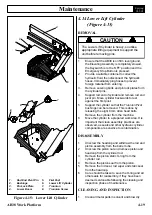
Figure 4-18: Telescopic Cylinder
end of thread and secure with circlip.
5.
Lubricate the piston seal and install the piston
and rod assembly in the barrel tube.
6.
Thread headcap onto barrel tube and hand
tighten, then turn 1/4 turn further.
7.
Install the upper cylinder Overcentre valve.
INSTALLATION
NOTE:
Before installing Lift Cylinder check cylinder
pins and bearings for wear and replace if necessary.
1.
Install barrel end bearing (if removed)
2.
Lift the barrel end of the cylinder into place and
push the cylinder pin in.
NOTE:
Take care in aligning the holes so that the pin
can be pushed in by hand. Bearings will be damaged
if holes are not properly aligned and the pin is forced.
3.
Align pin lock plate on cylinder pin with hole in
the mast and push the cylinder pin completely
in. Fix pin lock plate with bolt.
4.
Install rod end bearings (if removed).
5.
Lift rod end of cylinder into place and insert pin.
Install pin lock plate. Fix pin lock plate with bolt.
6.
Test with weight at rated platform load to check
system operation.
1.
Upper Boom
2.
Pin Lock Plate
3.
Circlip
4.
Telescopic Cylinder
5.
Barrel End Pivot Pin
6.
Rod End Pivot Pin
7.
Telescopic Boom
7
4
3
6
1
2
5
Содержание AB38
Страница 2: ...ii AB38 Work Platform NOTES...
Страница 4: ...ii AB38 Work Platform NOTES...
Страница 6: ...iv AB38 Work Platform NOTES Foreword...
Страница 10: ...Contents Section IV AB38 Work Platform i NOTES...
Страница 14: ...Introduction Specifications Section 1 4 AB38 Work Platform NOTES 1 3...
Страница 17: ...Machine Preparation Section 2 3 AB38 Work Platform NOTES 2 7...
Страница 18: ...Machine Preparation Section 2 4 AB38 Work Platform 2 7 NOTES...
Страница 29: ...Operation Section 3 11 AB38 Work Platform NOTES 3 5...
Страница 30: ...Operation Section 3 12 AB38 Work Platform NOTES 3 5...
Страница 59: ...Maintenance Section 4 29 AB38 Work Platform NOTES 4 21...
Страница 60: ...Maintenance Section 4 30 AB38 Work Platform NOTES 4 21...
Страница 66: ...Troubleshooting Section 5 6 AB38 Work Platform 5 7 NOTES...
Страница 68: ...Schematics Section 6 2 AB38 Work Platform NOTES 6 0...
Страница 71: ...Schematics Section 6 5 AB38 Work Platform 6 1 6 1 Electrical Schematics J1 Harness Connections TOP VIEW...
Страница 72: ...Schematics Section 6 6 AB38 Work Platform 6 1 NOTES...
Страница 73: ...Electrical Schematic Schematics 6 7 AB38 Work Platform Section 6 1...
Страница 74: ...Electrical Schematic Schematics 6 8 AB38 Work Platform Section 6 1 TOP VIEW...
Страница 76: ...Schematics Section 6 10 AB38 Work Platform NOTES 6 2...
Страница 78: ...Section 6 2 6 12 AB38 Work Platform Schematics NOTES...
Страница 81: ...Illustrated Parts Breakdown Section 7 3 AB38 Work Platform 7 2...
Страница 83: ...Illustrated Parts Breakdown Section 7 5 AB38 Work Platform 7 2...
Страница 85: ...Illustrated Parts Breakdown Section 7 7 AB38 Work Platform 7 2...
Страница 87: ...Illustrated Parts Breakdown Section 7 9 AB38 Work Platform 7 2...
Страница 89: ...Illustrated Parts Breakdown Section 7 11 AB38 Work Platform 7 2 22...
Страница 91: ...Illustrated Parts Breakdown Section 7 13 AB38 Work Platform 7 2...
Страница 93: ...Illustrated Parts Breakdown Section 7 15 AB38 Work Platform 7 2...
Страница 95: ...Illustrated Parts Breakdown Section 7 17 AB38 Work Platform 7 2...
Страница 97: ...Illustrated Parts Breakdown Section 7 19 AB38 Work Platform 7 2...
Страница 99: ...Illustrated Parts Breakdown Section 7 21 AB38 Work Platform 7 2...
Страница 101: ...Illustrated Parts Breakdown Section 7 23 AB38 Work Platform 7 2...
Страница 103: ...Illustrated Parts Breakdown Section 7 25 AB38 Work Platform 7 2...
Страница 105: ...Illustrated Parts Breakdown Section 7 27 AB38 Work Platform 7 2...
Страница 107: ...Illustrated Parts Breakdown Section 7 29 AB38 Work Platform 7 2...
Страница 109: ...Illustrated Parts Breakdown Section 7 31 AB38 Work Platform 7 2...
Страница 111: ...Illustrated Parts Breakdown Section 7 33 AB38 Work Platform 7 2...
Страница 113: ...Illustrated Parts Breakdown Section 7 35 AB38 Work Platform 7 2...
Страница 115: ...Illustrated Parts Breakdown Section 7 37 AB38 Work Platform 7 2...
Страница 117: ...Illustrated Parts Breakdown Section 7 39 AB38 Work Platform 7 2...
Страница 119: ...Illustrated Parts Breakdown Section 7 41 AB38 Work Platform 7 2 8 9...
Страница 121: ...Illustrated Parts Breakdown Section 7 43 AB38 Work Platform 7 2...
Страница 123: ...Illustrated Parts Breakdown Section 7 45 AB38 Work Platform 7 2...
Страница 125: ...Illustrated Parts Breakdown Section 7 47 AB38 Work Platform 7 2...
Страница 127: ...Illustrated Parts Breakdown Section 7 49 AB38 Work Platform 7 2...
Страница 131: ...Illustrated Parts Breakdown Section 7 53 AB38 Work Platform 7 2 NOTES...
Страница 133: ...Technician s Print AB38 Work Platform Electrical Schematic...

