background image

Machine Preparation

Section

2-2

AB38 Work Platform

WARNING

2.7 Storage

No preparation is required for storage when the Work
Platform is in regular use. Regular maintenance per

Table 4-1

 should be performed.

If the work platform is to be placed in long term
storage (dead storage) use the following preservation
procedure.

PRESERVATION

1.

Clean painted surfaces. If the painted surface is
damaged, repaint.

2.

Fill the hydraulic tank to operating level 

with the

platform fully lowered.

 Fluid should be visible

on the Dip Stick. It is not recommended that the
hydraulic fluid be drained.

3.

Coat exposed portions of cylinder rods with a
preservative such as multipurpose grease and
wrap with barrier material.

4.

Coat all exposed unpainted metal surfaces with
preservative.

BATTERIES

1.

Disconnect the batteries.

2.

Disconnect the battery leads and secure to the
chassis.

Care should be taken, while disconnecting the
battery leads, that a short circuit does not occur.
i.e. grounding to the chassis with a spanner.

3.

Remove the batteries and place in alternate
service. Battery efficiencies are best realised
when used consistently.

2.6

When the AB38 is on the Truck it should then be
made secure.

1.

Chock the wheels of the AB38.

2.

Secure the work platform to the transport
vehicle with chains or straps of adequate load
capacity attached to the lifting lugs on the
chassis.

Overtightening of the chains or straps through
tie down lugs may result in damage to the
Work Platform.

CAUTION

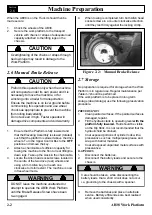
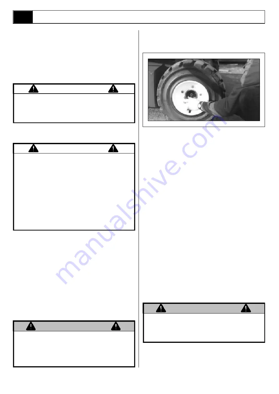
2.6 Manual Brake Release

Preform this operation only when the machine
will not operate under its own power and it is
necessary to move the machine, or for
winching onto a trailer for transportation.
Ensure the machine is on level ground before
commencing this operation and use wheel
chocks as appropriate to prevent the machine
from rolling inadvertently.
Do not exceed 3 mph. Faster speeds will
damage drive components and void warranty.

1.

Ensure that the Platform is fully lowered and
that the Elevating Assembly is slewed (rotated)
such that the platform is stowed above the drive
wheels. Turn the Upper Control Box to the 

OFF

position and remove the key.

2.

Attach a chain/cable of sufficient capacity for
towing the machine to the front or rear lifting/tie
down lugs. Take up the slack in the chain/cable.

3.

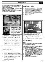
Locate the Allen head socket screws located in
the centre of the two drive (rear) wheels and
using a 6 mm Allen key, turn each one
clockwise to its full extent. The machine is now
in freewheel mode.

DO NOT leave the machine unattended or
attempt to operate the AB38 Work Platform
until the Brake Release Screws have been
re-engaged.

CAUTION

4.

When towing is completed, turn both Allen head
socket screws in a counter clockwise direction
until they rest firmly against the locking circlip.

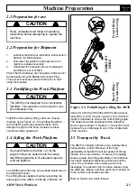
Figure 2-2 :  Manual Brake Release

WARNING

Содержание AB38

Страница 1: ...G The AB38N Machine has been re assessed to ensure compliance to the Machinery Directive 2006 42 EC The Machine rating has been changed from 2 People Indoors and Outdoors To 2 People Indoors and 1 Per...

Страница 2: ...ii AB38 Work Platform NOTES...

Страница 3: ...4 kW MODEL SERIAL NO MAX PLATFORM HEIGHT UNLADEN WEIGHT MAX PLATFORM LOAD MAX LATERAL FORCE MAX WIND SPEED MAX CHASSIS INCLINATION BATTERY VOLTAGE MAX GRADEABILITY CHARGER INPUT VOLTAGE MAX FORWARD S...

Страница 4: ...ii AB38 Work Platform NOTES...

Страница 5: ...ays in which service whether or not recommended by UpRightght can be done or the possible hazardous consequences of each conceivable way nor could UpRight investigate all ways Anyone using service pro...

Страница 6: ...iv AB38 Work Platform NOTES Foreword...

Страница 7: ...3 9 3 5 Notes 3 11 4 0 Maintenance 4 0 Introduction 4 1 Tools Required 4 1 4 1 Preventative Maintenance 4 1 Preventative Maintenance Table Key 4 2 Preventative Maintenance Report 4 2 4 2 Battery Main...

Страница 8: ...re 5 1 5 1 Troubleshooting Guides 5 2 5 2 Fault Codes 5 4 6 0 Schematics 6 0 Introduction 6 1 6 1 Electrical Schematics 6 3 6 2 Hydraulic Schematics 6 9 7 0 Illustrated Parts Breakdown 7 0 Introductio...

Страница 9: ...uit 4 14 4 13 Electric Motor Assembly 4 16 4 14 Drive Reduction Gearbox 4 17 4 15 Lower Lift Cylinder 4 19 4 16 Hydraulic Cylinder Component Breakdown 4 20 4 17 Upper Lift Cylinder 4 21 4 18 Telescopi...

Страница 10: ...Contents Section IV AB38 Work Platform i NOTES...

Страница 11: ...d from aluminium tubing and a safety drop bar is provided at the entrance Safety harness anchor points are also fitted in the floor of the platform The primary Control Box is fitted permanently within...

Страница 12: ...ng of the AB38 Work Platform is controlled by the ECU which controls the signals activating a double acting cylinder An Operator can Steer left or right by depressing the Rocker Switches on top of the...

Страница 13: ...side Turning Radius 2 40 m 7 87 ft Power Source 48V DC 4kW 8 X 6V 220Ah Batteries 48V DC 5 4HP 8 X 6V 220Ah Batteries System Voltage 48V 48V Battery Charger 48V 25A 220 110VAC 50 60 Hz 48V 25A 220 110...

Страница 14: ...Introduction Specifications Section 1 4 AB38 Work Platform NOTES 1 3...

Страница 15: ...rm and be certain that lifting apparatus is of adequate capacity to lift the platform The AB38 may be lifted by an overhead hoist crane in the following manner Four lifting straps capable of safely su...

Страница 16: ...d capacity attached to the lifting lugs on the chassis Overtightening of the chains or straps through tiedown lugs may result in damage to the Work Platform CAUTION 2 6 Manual Brake Release Preform th...

Страница 17: ...Machine Preparation Section 2 3 AB38 Work Platform NOTES 2 7...

Страница 18: ...Machine Preparation Section 2 4 AB38 Work Platform 2 7 NOTES...

Страница 19: ...is depressed The speed range within which the machine will drive is deter mined by whether or not the booms are raised If a boom is raised off the Boom Rest Limit Switch the current to the drive motor...

Страница 20: ...In the event of a power loss the two Boom Lift Cylinders are fitted with emergency lowering valves which allow the booms to be lowered at a controlled speed by an operator on the ground A Master Cyli...

Страница 21: ...he maximum side force must not exceed 400 N 90 ft lbs DO NOT increase wind loadings by fitting items such as sign boards flags etc to the cage or boom DISTRIBUTE all loads evenly on the platform See T...

Страница 22: ...engage Lower Boom lift functions Up Down 5 Drive Depress button to engage Drive functions Forward Reverse 6 Horn Depress button and hold to sound the horn 7 Slew Rotate Depress button to engage Slew f...

Страница 23: ...Operation Section 3 5 AB38 Work Platform 3 2 Figure 3 1 Controls Indicators 1 11 2 3 4 5 6 7 8 10 9 1 2 3 4 5 6 7...

Страница 24: ...ounting structure lift cylinders cables and hoses for leaks damage or erratic operation Check for missing or loose parts such as nuts bolts and circlips 14 Test that the Emergency Lowering Valves on e...

Страница 25: ...ead obstructions and when satisfied squeeze the red Interlock control on 3 4 WARNING the Joystick Slowly move the Joystick forward to ELEVATE Boom 1 The further the joystick is moved the faster the bo...

Страница 26: ...lling button on the upper control box see fig3 1 while moving the joystick forward or back to level the platform The switch should be operated in short bursts to level the platform slowly EMERGENCY SI...

Страница 27: ...ating Assembly first apply a 7 8 socket wrench to the shaft and turn to rotate the Elevating Assembly When finished remove the wrench MANUAL ROTATION 1 Ensure booms are lowered as far as possible usin...

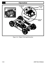
Страница 28: ...Operation Section 3 10 AB38 Work Platform 3 4 Figure 3 4 Manual Telescopic Retraction Valve Block Hydraulic Tank Hand Pump Valve Hand Pump Handle...

Страница 29: ...Operation Section 3 11 AB38 Work Platform NOTES 3 5...

Страница 30: ...Operation Section 3 12 AB38 Work Platform NOTES 3 5...

Страница 31: ...apable of reading Voltage Ohms and Amps 1 x Hydraulic Pressure Gauge Range 0 3000 PSI 4 1 Preventative Maintenance Table 4 1 The complete inspection consists of periodic visual and operational checks...

Страница 32: ...Grease all fittings 50h 30d Check for corrosion Remove and 250h 6m repaint NOTE Recommend Bolt Torques are shown in Table 4 3 Section 4 13 Preventative Maintenance Table Key Interval Daily each shift...

Страница 33: ...able contact surfaces to a bright metal finish whenever a cable is removed Basic Rule for maximum duty cycle of deep cycle traction batteries l Use the machine until it shows signs of weak slow perfor...

Страница 34: ...The Charger will turn on automatically after going through a self test sequence LED s will indicate the status of charging 4 The Charger indicates that the charge is complete when the batteries are fu...

Страница 35: ...evenly and sparingly every 10 hours or 7 days as per the intervals in Table 4 1 DO NOT subject this area to powerwashing HYDRAULIC OIL TANK AND FILTER Figure 4 2 Fluid Level With platform fully lowere...

Страница 36: ...nd safety glasses when handling hot oil The oil in the hydraulic system is under very high pressure which can easily cause severe cuts Obtain medical assistance immediately if cut by hydraulic oil MAI...

Страница 37: ...om 6 Push Lower Control Boom 1 Switch to DOWN and gradually lower the platform until Lower Boom is supported by the sling REMOVAL OF ELEVATING ASSEMBLY SUPPORT 1 Push Lower Control Boom 1 Switch to UP...

Страница 38: ...the Tilt Sensor until the bubble is centred 4 Elevate the platform until the Boom Rest Switch opens and depress the Interlock Switch on the Joystick Ask a colleague to push the tilt sensor base to te...

Страница 39: ...Maintenance Section 4 9 AB38 Work Platform 4 7 Figure 4 7 Tilt Sensor Figure 4 8 Boom Rest Limit Switch Elevating Assembly Switch Head Switch Body Lower Boom Upper Boom...

Страница 40: ...leaning solvent to remove built up contaminants and then blow out all passages with clean compressed air 2 Inspect the manifold for cracks thread damage and scoring where O rings seal against internal...

Страница 41: ...e Block 2 Solenoid Valve 3 Coil 4 Locking Nut 5 Fitting straight 6 Bonded Washer 7 Pressure Reduction Valve 8 Main Relief Valve 9 Pressure Test Point 10 Telescopic Retraction Valve 11 Cross Line Relie...

Страница 42: ...ntenance procedures on the Drive Motors ensure that the electric circuit is disconnected i e disconnect the batteries and unplug the charger It is also important that when dealing with batteries the p...

Страница 43: ...working hours or every two years Bearings All the bearings are fitted with a double shield and lubricated with high temperature grease Check for leaks vibration and noise If necessary replace with bea...

Страница 44: ...t can be assumed that the original problem is external to the motor WARNING DISASSEMBLY 1 Remove through bolts 2 Remove pulley end cover 3 Pull the armature out of the assembly in one swift motion 4 R...

Страница 45: ...load test can now be performed At rated voltage observe the no load current It should be less than 20 of the nameplate full load current Anything higher will indicate Brushes are not on neutral setti...

Страница 46: ...Bearing 3 Pulley End Cover 4 Pulley End Bearing 5 Armature 6 Commutator 7 Bearing 8 Stator Housing 9 Brush Housing Support 10 Commutator End Cover 11 Inspection Cover 12 Brush Holders 13 Brush Retaini...

Страница 47: ...o F 50o C 122o F VG 320 During oil change we recommend that the inside of the Gearcase is flushed out with flushing fluid recommended by the lubricant manufacturer Oil should be changed when hot to pr...

Страница 48: ...tely 0 9 Litres 0 23 Gallons US of oil To check this level rotate the Gearbox into the horizontal position with one of the filler drain plug holes in the 3 O Clock position and the other plug hole abo...

Страница 49: ...ove rod end pivot pin Move cylinder backwards to rest against the first post 5 Support the cylinder so that the Trunnion Pivot bushings can be removed This is done by releasing the eight 8 mm Allen he...

Страница 50: ...hould be used 2 Install a new piston seal on the piston 3 Install the headcap on the cylinder from the piston end 4 Install the piston piston nut and a new piston static O ring on the cylinder rod Scr...

Страница 51: ...and remove piston and headcap from the cylinder rod 3 Remove the piston static O ring from the cylinder rod 4 Remove the piston seal from the piston 5 Remove the rod seal rod wiper and static seal fr...

Страница 52: ...Unscrew the piston nut and remove piston and headcap from the cylinder rod 3 Remove the piston static O ring from the cylinder rod 4 Remove the piston seal from the piston 5 Remove the rod seal rod w...

Страница 53: ...ace Push the cylinder pin in NOTE Take care in aligning the holes so that the pin can be pushed in by hand If holes are not properly aligned and the pin is forced in the bearings will be damaged 3 Ali...

Страница 54: ...inder barrel 4 Lubricate the piston seal and install the rod Figure 4 19 Steer Cylinder piston assembly in the barrel tube 6 Thread the headcap onto the free end of the barrel tube and hand tighten th...

Страница 55: ...shaft for signs of scoring pits excessive wear or polishing Scratches or pits deep enough to catch a fingernail are unacceptable Polishing is a sign of uneven loading and if sufficiently polished the...

Страница 56: ...er seals for reassembly if they have been deemed serviceable following the cleaning and inspection phase of maintenance CLEANING AND INSPECTION 1 Clean all metal parts in solvent and blow dry with fil...

Страница 57: ...direction Continue this until and for 30 seconds after the Platform comes to a stop Care must be taken that the Platform Cage does not impact on the ground The above two procedures have the effect of...

Страница 58: ...s the pressure setting Turning the screw anticlockwise reduces the setting and allows the boom to creep downwards Adjust the spring setting until the boom just begins to creep downwards d Screw the ad...

Страница 59: ...Maintenance Section 4 29 AB38 Work Platform NOTES 4 21...

Страница 60: ...Maintenance Section 4 30 AB38 Work Platform NOTES 4 21...

Страница 61: ...the elevating assembly must be securely supported by overhead cranes or equivalent of suitable capacity WARNING GENERAL PROCEDURE As all problems which require troubleshooting will to some extent be u...

Страница 62: ...seals in Lift cylinder return line replace Cylinders CYL1 the seal kit if necessary CYL2 Telescope 3 Overcentre Valve Check for contamination leaking and clean Check that internally or O Rings are in...

Страница 63: ...elling is levelling closed required See Section 4 19 erratic or circuit irregular 2 Cage damaged Replace throughout hole centres are the lift cycle out of position 3 Damaged Remove and inspect Overcen...

Страница 64: ...ult code is still displayed you may have a faulty upper or lower control box consult the error code list to identify the problem component and replace if necessary For fault codes 51 69 the following...

Страница 65: ...ocker not in neutral at power up 34 Lower Control Slew Switch ON at power up 36 Lower Control Telescope Switch ON at power up 37 Lower Control Lower Boom Switch ON at power up 38 Lower Control Upper B...

Страница 66: ...Troubleshooting Section 5 6 AB38 Work Platform 5 7 NOTES...

Страница 67: ...n contains electrical and hydraulic power schematics and associated information for maintenance purposes INDEX Page Electrical Assy J1 Harness 6 3 Electrical Assy J2 Harness 6 4 Electrical Assy J1 Har...

Страница 68: ...Schematics Section 6 2 AB38 Work Platform NOTES 6 0...

Страница 69: ...B1 WHITE 25 C1 BLACK 2 A2 NOT USED 14 B2 NOT USED 26 C2 ORANGE 3 A3 GREEN 15 B3 NOT USED 27 C3 BLACK 4 A4 BLACK 16 B4 NOT USED 28 C4 WHITE BLACK 5 A5 BROWN 17 B5 YELLOW 29 C5 GREY 6 A6 NOT USED 18 B6...

Страница 70: ...Schematics Section 6 4 AB38 Work Platform 6 1 Electrical Schematics 6 1 1 1 1 12 12 12 A B C F G F M K J L B P T S U V N E R D C A 1 2 3 6 5 4 1 2 3 5 6 4...

Страница 71: ...Schematics Section 6 5 AB38 Work Platform 6 1 6 1 Electrical Schematics J1 Harness Connections TOP VIEW...

Страница 72: ...Schematics Section 6 6 AB38 Work Platform 6 1 NOTES...

Страница 73: ...Electrical Schematic Schematics 6 7 AB38 Work Platform Section 6 1...

Страница 74: ...Electrical Schematic Schematics 6 8 AB38 Work Platform Section 6 1 TOP VIEW...

Страница 75: ...of tele On side of boom in the case of power manifold block failure Delivers 15cc stroke MMB Main manifold Contains the directional On hydraulic block control valves and relief reservoir in valves tha...

Страница 76: ...Schematics Section 6 10 AB38 Work Platform NOTES 6 2...

Страница 77: ...1 A B V12 CYL3 TELE V11 A B V13 V10 RV MOT1 TP A6 B6 A2 B2 A3 B3 A4 B4 A5 B5 A1 B1 BRAKE CYL4 STEER A B BRK BRK CYL6 SLAVE A V15 B F C F E CYL5 MASTER A V14 B F C F E V9 V8 V7 V6 V5 V4 V3 V2 V1 HP P T...

Страница 78: ...Section 6 2 6 12 AB38 Work Platform Schematics NOTES...

Страница 79: ...embly Rotator 7 10 Wheel Hub Assembly 7 12 Drive Reduction Gearbox Assembly 7 14 Traction Motor Assembly 7 16 Motor Pump Assembly 7 18 Rear Front Wheel Kit 7 20 Worm Drive Unit Slew Bearing Assembly 7...

Страница 80: ...530 000 Motor Pump Assembly 500494 000 Rear Front Wheel Assembly 500284 001 Pinion Gearbox Slew Bearing Assy 500261 000 Manifold Block Assembly 058460 000 Lower Lift Cylinder Assembly 058462 000 Upper...

Страница 81: ...Illustrated Parts Breakdown Section 7 3 AB38 Work Platform 7 2...

Страница 82: ...0 TILT SENSOR 1 17 057530 000 MOTOR PUMP ASSEMBLY 1 18 057578 000 REAR WHEEL NUT M14 10 19 057668 001 REAR WHEEL TYRE RIM ASSY 2 20 057667 003 FRONT WHEEL TYRE RIM ASSY 2 21 057666 000 FRONT WHEEL NUT...

Страница 83: ...Illustrated Parts Breakdown Section 7 5 AB38 Work Platform 7 2...

Страница 84: ...1 16 058734 000 AB38 MASTER LEVELLING CYLINDER 1 17 058735 000 AB38 SLAVE LEVELLING CYLINDER 1 18 058461 000 AB38 TELESCOPIC CYLINDER 1 19 058056 000 PIN LOCK PLATE 14 056060 020 BOLT M10 x 20 mm 14 0...

Страница 85: ...Illustrated Parts Breakdown Section 7 7 AB38 Work Platform 7 2...

Страница 86: ...ADDER LOCKING LATCH 1 8 057348 000 LADDER 1 9 501886 000 OVERLOAD UNIT Ansi 509791 000 1 10 056066 012 M12 NYLOCK NUT 2 11 056069 016 M16 WASHER 8 12 503101 045 M16 X 45 HEX HEAD SCREW 8 13 056069 012...

Страница 87: ...Illustrated Parts Breakdown Section 7 9 AB38 Work Platform 7 2...

Страница 88: ...5 034 HANDLE 1 6 500905 030 DRIVE SHAFT 1 7 057524 000 DROP BAR ASSY 1 8 057521 001 CAGE RAIL ASSY 1 9 501970 000 WELDMENT CAGE BASE 1 10 501886 000 OVERLOAD UNIT Ansi 509791 000 1 11 058494 040 M12 X...

Страница 89: ...Illustrated Parts Breakdown Section 7 11 AB38 Work Platform 7 2 22...

Страница 90: ...7669 000 ITEM PART NO DESCRIPTION QTY 1 057665 000 WHEEL HUB 1 2 057664 000 THRUST BEARING 1 3 057662 000 PIVOT BOSS 1 4 057663 000 PIVOT PIN 1 5 057585 000 COVER PLATE 1 6 057584 000 OUTER HUB BEARIN...

Страница 91: ...Illustrated Parts Breakdown Section 7 13 AB38 Work Platform 7 2...

Страница 92: ...IP 3 28 SUN PINION 1 29 O RING 1 30 BEARING 1 31 RETAINING RING 1 32 RETAINING RING 1 NOTE ITEMS 5 7 8 11 12 13 15 29 44 46 FORM THE SEAL KIT FOR THE DRIVE REDUCTION GEARBOX ASSEMBLY THE PART NUMBER F...

Страница 93: ...Illustrated Parts Breakdown Section 7 15 AB38 Work Platform 7 2...

Страница 94: ...ITEM PART NO DESCRIPTION QTY 1 MOTOR MOUNTING FACE 1 2 SEAL 1 3 CIRCLIP 1 4 BEARING 1 5 COOLING FAN 1 6 COMMUTATOR 1 7 BEARING 1 8 FIELD WINDINGS 1 9 COMMUTATOR COVER 1 10 BRUSH BOXES SUPPORT 1 11 EN...

Страница 95: ...Illustrated Parts Breakdown Section 7 17 AB38 Work Platform 7 2...

Страница 96: ...IT 1 2 058847 000 COUPLING 1 3 OIL SEAL 1 4 PUMP MOUNTING FACE 1 5 CIRCLIP 1 6 BEARING 1 7 CIRCLIP 1 8 CIRCLIP 1 9 COOLING FAN 1 10 COMMUTATOR 1 11 BEARING 1 12 COMMUTATOR COVER 1 13 BRUSH HOUSING SUP...

Страница 97: ...Illustrated Parts Breakdown Section 7 19 AB38 Work Platform 7 2...

Страница 98: ...L NUT M16 10 4 057667 003 FRONT WHEEL TYRE RIM ASSY 2 REAR FRONT WHEEL KIT NON MARKING ITEM PART NO DESCRIPTION QTY 1 057578 000 WHEEL NUT M14 10 2 058971 000 REAR WHEEL TYRE RIM ASSY 2 3 057666 000 W...

Страница 99: ...Illustrated Parts Breakdown Section 7 21 AB38 Work Platform 7 2...

Страница 100: ...G ASSEMBLY 500284 001 ITEM PART NO DESCRIPTION QTY 1 500284 000 AB38 WORM DRIVE UNIT SLEW 1 BEARING ASSEMBLY 500280 000 BOLT 5 8 11 UNC x 3 1 2 16 500281 000 WASHER M16 HARDENED 16 2 500285 000 AB38 S...

Страница 101: ...Illustrated Parts Breakdown Section 7 23 AB38 Work Platform 7 2...

Страница 102: ...AIN RELIEF VALVE 1 9 500261 002 MANUAL TELE RETRACTION VALVE 1 10 500261 004 TELE RETRACTION VALVE LEVER 1 11 057539 000 CROSS LINE RELIEF VALVE 2 12 BONDED SEAL VARIOUS 12 13 057358 000 ADAPTOR 1 4 x...

Страница 103: ...Illustrated Parts Breakdown Section 7 25 AB38 Work Platform 7 2...

Страница 104: ...SEE NOTE U RING ROD SEAL 1 7 SEE NOTE ROD SEAL 1 8 SEE NOTE WIPER 1 9 SEE NOTE BACK UP 0 RING 1 10 SEE NOTE O RING 1 11 SPACER 1 12 SEE NOTE PISTON O RING 1 13 PISTON HEAD 1 14 SEE NOTE PISTON SEAL 1...

Страница 105: ...Illustrated Parts Breakdown Section 7 27 AB38 Work Platform 7 2...

Страница 106: ...RRENT 3 058728 000 SINGLE OVERCENTRE VALVE 1 4 END CAP 1 5 ROD AND END PIVOT 1 6 SEE NOTE U RING ROD SEAL 1 7 SEE NOTE ROD SEAL 1 8 SEE NOTE WIPER 1 9 SEE NOTE BACK UP 0 RING 1 10 SEE NOTE O RING 1 11...

Страница 107: ...Illustrated Parts Breakdown Section 7 29 AB38 Work Platform 7 2...

Страница 108: ...HECK VALVE 1 4 END CAP 1 5 ROD AND END PIVOT 1 6 SEE NOTE U RING ROD SEAL 1 7 SEE NOTE ROD SEAL 1 8 SEE NOTE WIPER 1 9 SEE NOTE 0 RING 1 10 057048 000 GREASE NIPPLE 1 11 SPACER 1 12 SEE NOTE PISTON O...

Страница 109: ...Illustrated Parts Breakdown Section 7 31 AB38 Work Platform 7 2...

Страница 110: ...EM PART NO DESCRIPTION QTY 1 CYLINDER BODY 1 2 CYLINDER ROD 1 3 SEE NOTE PISTON SEAL 1 4 END CAP 1 5 SEE NOTE WIPER 1 6 SEE NOTE ROD SEAL 1 7 SEE NOTE O RING 1 8 057048 000 GREASE NIPPLE 2 NOTE ITEMS...

Страница 111: ...Illustrated Parts Breakdown Section 7 33 AB38 Work Platform 7 2...

Страница 112: ...VALVE 1 4 END CAP 1 5 ROD AND END PIVOT 1 6 SEE NOTE U RING ROD SEAL 1 7 SEE NOTE ROD SEAL 1 8 SEE NOTE WIPER 1 9 SEE NOTE BACK UP 0 RING 1 10 SEE NOTE 0 RING 1 11 SPACER 1 12 SEE NOTE PISTON O RING...

Страница 113: ...Illustrated Parts Breakdown Section 7 35 AB38 Work Platform 7 2...

Страница 114: ...R CONTROL UNIT ASSEMBLY 501862 000 ITEM PART NO DESCRIPTION QTY 1 501894 000 HARNESS LC2 TO MTR CNTRL B 1 2 501895 000 HARNESS FWD 3 TO FWD 5 1 3 501895 000 HARNESS REV 3 TO REV 5 1 4 501895 000 HARNE...

Страница 115: ...Illustrated Parts Breakdown Section 7 37 AB38 Work Platform 7 2...

Страница 116: ...WER CONTROLBOX ASSEMBLY 500490 000 Harnesses are not part of this assembly ITEM PART NO DESCRIPTION QTY 1 501867 000 E STOP SWITCH C W CONTACT BLOCK 1 2 501872 000 ANALOG ROCKER 1 3 501870 000 OVERLAY...

Страница 117: ...Illustrated Parts Breakdown Section 7 39 AB38 Work Platform 7 2...

Страница 118: ...LLER 1 2 501865 000 PC BOARD ASSY 1 3 501866 000 KEY SWITCH 1 4 501867 000 E STOP SWITCH C W CONTACT BLOCK 1 5 501869 000 OVERLAY DECAL 1 6 501881 000 UPPER CONTROL BOX BOX ONLY 1 7 501882 000 JOYSTIC...

Страница 119: ...Illustrated Parts Breakdown Section 7 41 AB38 Work Platform 7 2 8 9...

Страница 120: ...TOR CONTROLLER 11 502589 000 HARNESS LH MOTOR MOTOR CONTROLLER B 1 HARNESS LH MOTOR REVERSE CONTACTOR 1 HARNESS LH MOTOR MOTOR CONTROLLER A2 1 HARNESS LH MOTOR FORWARD CONTACTOR 1 12 502590 000 HARNES...

Страница 121: ...Illustrated Parts Breakdown Section 7 43 AB38 Work Platform 7 2...

Страница 122: ...B90 MANIFOLD TO SLEW MOTOR 11 500351 000 HOSE ASSY 1 4 M1T 1750 mm 1 B90 B90 MANIFOLD TO LOWER LIFT CYLINDER 12 500351 000 HOSE ASSY 1 4 M1T 1750 mm 1 B90 B90 MANIFOLD TO LOWER LIFT CYLINDER 13 500352...

Страница 123: ...Illustrated Parts Breakdown Section 7 45 AB38 Work Platform 7 2...

Страница 124: ...INSTR 1 18 058530 000 DECAL MEETS ANSI REQUIREMENTS 1 19 058534 000 DECAL BATTERIES ARE 2 COUNTERWEIGHT 20 058533 000 DECAL DO NOT ADJUST SWITCHES 2 21 058761 000 DECAL S W L LARGE ANSI 1 22 057434 0...

Страница 125: ...Illustrated Parts Breakdown Section 7 47 AB38 Work Platform 7 2...

Страница 126: ...7430 000 DECAL EXPLOSION HAZARD 2 9 057692 000 DECAL IMPORTANT BEFORE USING 1 10 058472 000 NAMEPLATE 1 11 500467 000 DECAL HANDPUMP 1 12 058881 001 DECAL HAZARD TAPE 2 13 058080 000 DECAL CAGE LEVELL...

Страница 127: ...Illustrated Parts Breakdown Section 7 49 AB38 Work Platform 7 2...

Страница 128: ...438 001 DECAL LOWER CONTROL COVER 1 21 500422 001 SERVICE PARTS MANUAL 1 DECAL KIT French CE 500206 003 DECAL KIT German CE 500206 002 ITEM PART NO DESCRIPTION QTY 1 500264 000 DECAL UpRight AB38 BOOM...

Страница 129: ...Illustrated Parts Breakdown Section 7 51 AB38 Work Platform 7 2 DECAL KIT French CE 500206 003 DECAL KIT German CE 500206 002...

Страница 130: ...OR PETROL 7 058259 004 AB38 OPTION GENERATOR DIESEL 8 500494 001 AB38 OPTION NON MARKING WHEELS WHITE TYRES The options outlined opposite are available from UpRight when ordering a new machine or as a...

Страница 131: ...Illustrated Parts Breakdown Section 7 53 AB38 Work Platform 7 2 NOTES...

Страница 132: ...443 6600 FAX 1 559 268 2433 www upright com Europe TEL 44 0 845 1550 058 FAX 44 0 195 2299 948 Local Distributor Lokaler Vertiebsh ndler Distributeur local El Distribuidor local Il Distributore local...

Страница 133: ...Technician s Print AB38 Work Platform Electrical Schematic...

Отзывы:

Похожие инструкции для AB38