


www.uponor-usa.com • www.uponor.ca
12
Uponor Climate Co˘ntrol™ - Multifunction Installation Guide
13
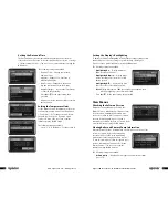
Boiler Connections
When connecting to boilers or any type of heating devices that require
an input or signal to start, an Uponor Boiler Control (A9012010) is required.
This boiler control provides two dry contact outputs and B terminals.
Terminal A is typically wired to start a heating device and is connected to
the Climate Co˘ntrol - Multifunction controller using the proper-length Cat5
wire with RJ45 connectors. (See
Figure 4-7
.)
The boiler relay comes with a set of LEDs to show the status of the device.
The A and B lights will turn red when the Multifunction Climate Co˘ntrol
unit turns either of the relays on for heat. The green LED will illuminate
when the relay box is connected correctly to the Climate Co˘ntrol -
Multifunction unit. A manual override switch for each set of terminals
(A and B) is located inside the cover. These will operate when the relay is
not connected to the control via a Cat5 cable.
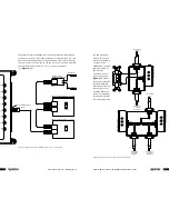
Figure 4-7
: Typical wiring of a heating device using an Uponor Boiler Control (A9012010)
for space heating
Auto
Man
A Terminal
B Terminal
A
B
Power
Space
Heating
High Temp
DHW
Typical heating device (e.g., boiler)
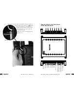
Top View
Side View
On
Tx
Run
Rx
Port 1
Input 1
Operate
MMI
Port 8
Input 8
Port 3
Port 2
Port 4
Port 5
Input 2
Input 3
Input 4
Input 5
Port 6
Input 6
Port 7
Input 7
Rx
Tx
Intercon
Boiler Control (A9012010)
To Climate Co˘ntrol Main Panel
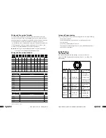
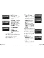
Multiple Boiler Stages
The Climate Co˘ntrol - Multifunction controller can run multiple boiler stages
(up to four) to optimize and regulate the proper amount of heat based
on outdoor temperature and loads. (See
Figure 4-8
.) As the temperature
differential increases between the supply and return sensors, the Climate
Co˘ntrol - Multifunction system will turn on an additional boiler. As the
differential decreases, the controller will turn off and rotate usage of the
boilers to ensure that the run time on each is equal.
Figure 4-8
: Typical wiring of four boiler stages
Man
A Terminal
Auto
B Terminal
A Terminal
Man
B Terminal
Auto
Heating Device 2
Heating
Space
Top View
Heating Device 4
Space
Heating
Top View
On
Tx
Run
Rx
Port 1
Input 1
Operate
MMI
Port 8
Input 8
Port 3
Port 2
Port 4
Port 5
Input 2
Input 3
Input 4
Input 5
Port 6
Input 6
Port 7
Input 7
Rx
Tx
Intercon
Boiler Control (A9012010)
Boiler Control (A9012010)
Heating Device 1
Heating
Space
Heating Device 3
Space
Heating
To Climate Co˘ntrol Main Panel