


www.uponor-usa.com • www.uponor.ca
10
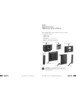
Uponor Climate Co˘ntrol™ - Multifunction Installation Guide
11
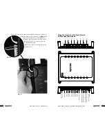
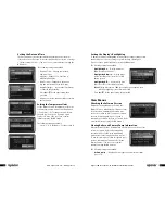
The control's left side has inputs using push-style connectors, so the use of
a small tip screwdriver is not required. (See
Figure 4-6
.)
These connectors require dry-contact inputs from
switching relays, thermostats or any other similar
devices. The bottom four connectors are fully
programmable outputs.
When active, LEDs for the inputs and outputs
will turn green.
On
Tx
Ru
n
Rx
Po
rt
1
Input
1
Ope
ra
te
MMI
Po
rt
8
Input
8
Po
rt
3
Po
rt
2
Po
rt
4
Po
rt
5
Input
2
Input
3
Input
4
Input
5
Po
rt
6
Input
6
Po
rt
7
Input
7
Rx
Tx
Intercon
Expansion C
onnec
to
r
(future)
24
VA
C IN
Input
1
Input
2
Input
3
Input
4
Input
8
Input
5
Input
7
Input
6
Pr
ogrammable Output
1
Display Unit C
onnec
tor
Po
rt
1
Pr
ogrammable Output
2
Pr
ogrammable Output
3
Pr
ogrammable Output
4
Outdoor Sensor
Po
rt
2
Po
rt
3
Po
rt
4
Po
rt
5
Po
rt
6
Po
rt
7
Po
rt
8
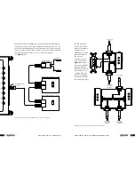
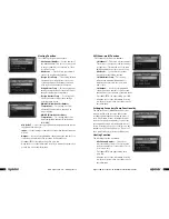
Wiring Connections for the Climate Co˘ntrol -
Multifunction Control Board
Figure 4-6
Figure 4-6