


www.uponor-usa.com • www.uponor.ca
28
Uponor Climate Co˘ntrol™ Zoning System Installation Guide
29
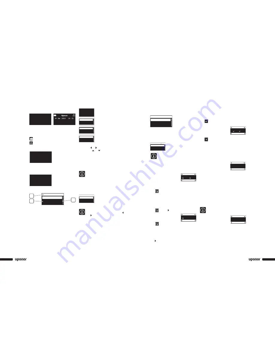
Information Menu
The Information menu provides information about rooms,
alarms/error messages and settings.
Information Menu: Room Information
1. Uponor screen
>
Main Menu
>
Information
>
Rooms
2.
>
Select the desired room.
>
Press OK.
The number at the beginning of the room name
on the display means: First digit: base unit.
Second and third digits: number of the first
channel controlled by this thermostat
(01, 02, 03, etc.). If several terminals are
controlled by the thermostat, only the lowest
terminal number is displayed.
Room Temperature
When room
information is
accessed, the screen displays room
setpoint and measured temperature.
The temperature setpoint is 69.8°F.
If the temperature set on the thermostat
is outside the allowed temperature range
for the room, the limitation temperature
will be displayed as setpoint.
The measured temperature is 70.16°F.
3.
>
to open the next screen.
ECO (Economy)
This screen displays
the temperature
setting for the room when it is in ECO
mode. (Current setting is 66.2°F.)
Current status:
COMF: Comfort mode.
ECO: Economy mode
4.
>
to open the next screen
Battery and Communication Status
Battery and communication status are indicated
with a √ or X.
• Battery: The batteries are
sufficiently charged.
• Signal: Radio signal from the
thermostat
is good.
• Battery: The batteries are low.
• Signal: Radio signal from the
thermostat and the antenna is faulty.
Thermostat and Actuator Status
Yes: The thermostat is calling for heat.
No: The thermostat is reporting that the
room temperature is satisfied.
Open: The actuators
are powered
and open or opening.
Closed: There is no power to the
actuators and they are closed
or closing.
The minimum temperature setpoint of
the room is set at 53.6°F.
The maximum temperature setpoint of
the room is set at 78.8°F.
Actuator Status
This screen is only displayed during installation.
OK: Normal
operation
Alarm: A short circuit or similar problem
is reported.
Alarms
System
Rooms
Information
1.07 Gym
1.02 Living
Room List
Battery
1.02 Living
More
Signal
Measured
Set Point
1.02 Living
More
69.8˚F
70.16˚F
StatCall: No Act.: Closed
1.02 Living
More
Min: 53.6˚F Max: 78.80
Status
ECO Temp
1.02 Living
More
66.2˚F
COMF
Status
Statcall
Act.
Min
Max
Interface Screens
Uponor Screen
• Pressing any button activates backlighting.
• To go to the main menu, press OK.
Uponor Screen Icons
Vacation mode is activated.
An alarm/error message is present.
The outdoor temperature is displayed if the system is
fitted with an outdoor temperature sensor.
The Interface menu displays indoor temperature; it will
also display outdoor temperature if the system is fitted
with an outdoor temperature sensor.
Main Menu
1. Upper banner: Menu heading
2. Information zone: The selected line is highlighted.
3. Scroll bar
How to Access and Navigate the Menu
Uponor
14 Jun 2008 2 : 00
1.
>
Press OK.
Vacation Mode
Settings
Information
Main Menu
2.
>
Information
>
Press OK.
Alarms
System
Rooms
Information
3.
>
Rooms
>
Press OK.
1.07 Gym
1.02 Living
Room List
4.
>
Select the desired room.
>
Press OK.
• Display the desired information using the navigation
keys. Use and to display the previous/next
screen. Use and to display the previous/next
thermostat.
• To go back to the room list, press OK.
Access Level
This parameter allows the user to set or select the
access level. Two levels are available: basic or advanced.
The basic level allows the user to view some
basic information, but not modify the settings.
Recommended for use in a public location or a
rented accommodation, such as a hotel room.
The advanced level allows users to
modify settings.
1.
>
Uponor screen
>
Main Menu
>
Settings
>
System
Parameters
>
Access Level selection
Advanced
Basic
Access Level
2.
>
Basic or Advanced
>
Press OK.
To switch from Basic to Advanced Level:
On the Uponor screen, simultaneously press
and for 10 seconds.
Screen Advanced and OK appears. Press OK to put the
system is in Advanced mode.
Uponor
14 Jun 2008 2 : 00
Uponor
10 Nov 2008 5 : 19
Outdoor 32
¡
F
Uponor
20 Nov 2008 5 : 19
Outdoor 32
°
F
Indoor Average 70.16
°
F
Vacation Mode
Settings
2
3
1
Information
Main Menu
Actuator: Alarm
1.02 Living
More
Actuator