background image

5

Industrial/EasyLAN 100i Interface Kit for XP – Installation Instructions Ed. 1

Chapter 2     Installation

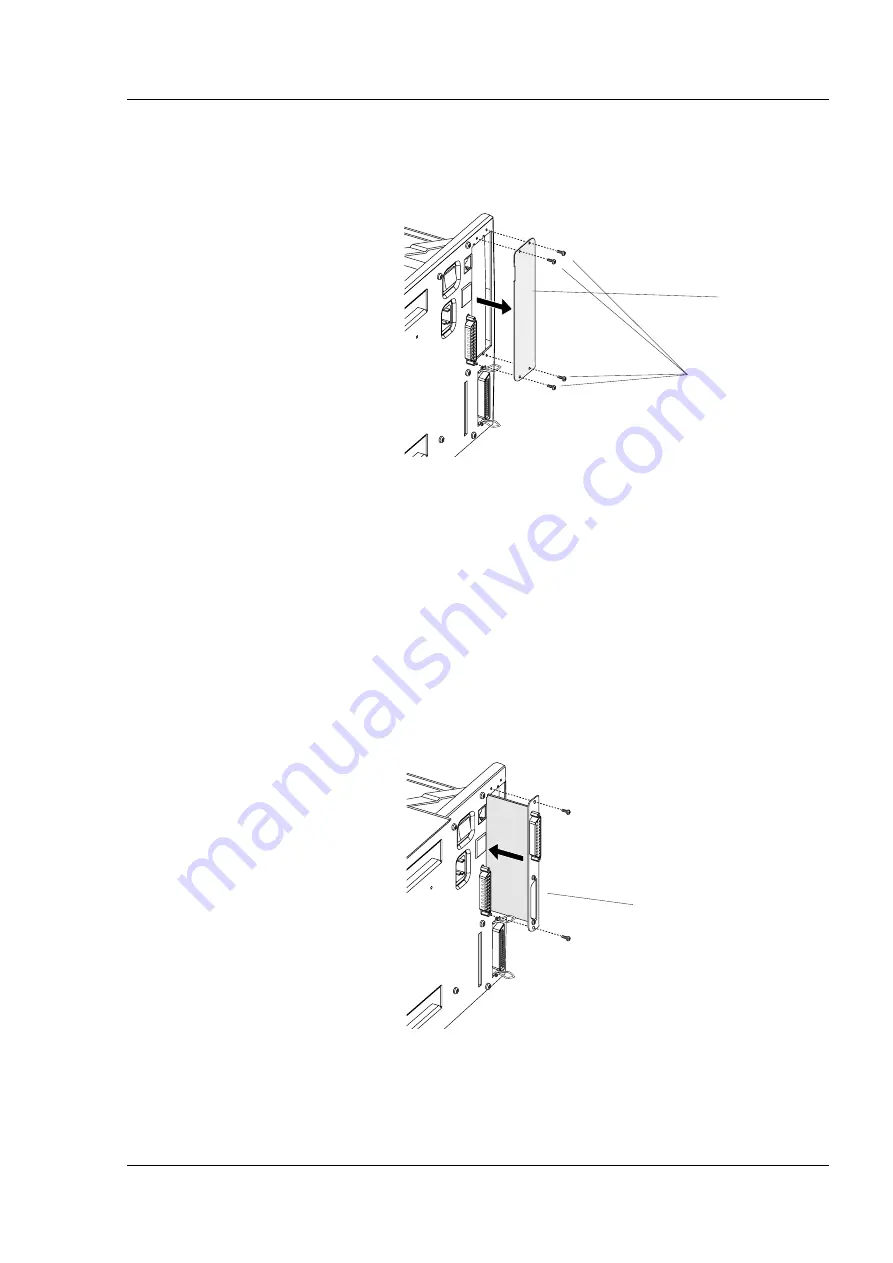
#T10 Torx screws (4x)

Cover Plate

•    Remove the four #T10 Torx screws that hold the interface 

cover plate above the parallel interface connector on the 
printer’s rear plate. Remove the cover plate.

•   Save the cover plate for possible later use. Keep the 

screws.

•    Insert the Industrial Interface Board into the slot previously 

covered by the cover plate. It does not matter in position 
(left/right) you fi t the two boards, but we recommend to fi t 
the Industrial interface board to the left and the EasyLAN 
100i interface board to the right (as seen from behind) for 
easiest access to the Test button on the EasyLAN 100i inter-
face board.

•    Check that the top and bottom edges of the board fi t into the 

two square cut-outs in the rear plate.

Step-by-Step Instruc-
tions, cont.

Industrial Interface Board

Содержание Intermec EasyLAN 100i

Страница 1: ...Industrial EasyLAN100i InterfaceKitforXP P N 1 960557 00 Edition 1 September 2001 Installation Instructions ...

Страница 2: ... 18 Contents Information in this manual is subject to change without prior notice and does not represent a commitment on the part of Intermec Printer AB Copyright Intermec Printer AB 2001 All rights reserved Published in Sweden The word Intermec the Intermec logo EasyCoder EasyLAN and Fingerprint are either trademarks or registered trade marks of Intermec Technologies Corp DOS Ethernet HP JetAdmin...

Страница 3: ...es you with the most advanced network management capabilities ever offered The EasyLAN 100i interface is designed to accommodate your network With the most robust network systems support ever offered your label printers will be up and running on your net work in minutes Save time space and money by putting the printer where you need it No need for a dedicated PC work station or long serial or para...

Страница 4: ...01 XP Firmware Intermec Fingerprint v7 60 or later The kit contains One Industrial Interface Board One EasyLAN 100i Ethernet Interface Board One flat cable One CD ROM with software and manuals This Installation Instructions booklet The only tool required for the installation is a T10 Torx screwdriver Installation Kit Firmware Require ments ...

Страница 5: ...d wires Do not open the electronics compartment before the printer is switched off and safely disconnected from any AC supply Open the right hand door Remove the four T10 Torx screws along the lower edge of the cover over the electronics compartment Remove the four T10 Torx screws that hold the upper edge of the same cover Remove the cover and put it aside on a soft cloth or similar to avoid scrat...

Страница 6: ...p the screws Insert the Industrial Interface Board into the slot previously covered by the cover plate It does not matter in position left right you fit the two boards but we recommend to fit the Industrial interface board to the left and the EasyLAN 100i interface board to the right as seen from behind for easiest access to the Test button on the EasyLAN 100i inter face board Check that the top a...

Страница 7: ...4 IC305 P32 P35 1 971600 01 P01 C7 R56 R55 R54 R53 R52 R3 R2 R1 JP1 IC7 IC6 IC2 IC1 C15 C14 C13 C12 C11 C6 C5 C4 C3 C2 C1 C8 C9 C10 C20 C21 C22 C23 C24 C25 C26 C27 D1 F1 F2 F3 F4 F5 F6 F7 F8 F9 F10 F11 F12 F13 F14 IC3 IC4 IC8 IC9 IC10 IC11 IC12 IC13 IC14 IC15 IC16 IC17 IC18 JP2 P1 P2 P3 P4 R4 R5 R6 R7 R10 R11 R12 R13 R14 R15 R16 R17 R18 R19 R20 R21 R22 R23 R24 R25 R26 R27 R28 R29 R30 R31 R32 R33 R...

Страница 8: ...s compartment Connect the power cord Now you have one Industrial interface and one EasyLAN 100i interface connector on the printer s rear plate in addi tion to the standard serial interface uart1 and the stand ard parallel interface centronics Connect the interface cables and switch on the power Step by Step Instruc tions cont P81 P1 P31 Cable CPU board Industrial Interface EasyLAN 100i Industrial...

Страница 9: ...of the port PORTIN returns the value 1 true else the value 0 false Signal Description Min Typical Max Vin High Input Voltage High 10V 24V 40V Vin Low Input Voltage Low 1V 0V 1V Connector Configuration Pin Signal Name Description Fingerprint Ref No 10 IN1A Anode Opto In Channel 1 101 40 IN1K Cathode Opto In Channel 1 26 IN2A Anode Opto In Channel 2 102 11 IN2K Cathode Opto In Channel 2 41 IN3A Anod...

Страница 10: ...V Connector Configuration Pin Signal Name Description Fingerprint Ref No 20 Out1c Collector Opto Out Channel 1 221 5 Out1e Emitter Opto Out Channel 1 35 Out2c Collector Opto Out Channel 2 222 21 Out2e Emitter Opto Out Channel 2 6 Out3c Collector Opto Out Channel 3 223 36 Out3e Emitter Opto Out Channel 3 22 Out4c Collector Opto Out Channel 4 224 7 Out4e Emitter Opto Out Channel 4 37 Out5c Collector...

Страница 11: ... Breaking Capacity Connector Configuration Pin Signal Name Description Fingerprint Ref No 16 REL1nc Relay 1 Normally Closed 201 1 REL1no Relay 1 Normally Open 31 REL1com Relay 1 Common 17 REL2nc Relay 2 Normally Closed 202 2 REL2no Relay 2 Normally Open 32 REL2com Relay 2 Common 18 REL3nc Relay 3 Normally Closed 203 3 REL3no Relay 3 Normally Open 33 REL3com Relay 3 Common 19 REL4nc Relay 4 Normall...

Страница 12: ...connect the printer to the network via the EasyLAN 100i interface board Using a category 5 unshielded twisted par cable or better connect the EasyLAN 100i interface board to your Local Area Network LAN Refer to Chapter 4 for instructions on how to set up the EasyLAN 100i interface Serial Number Label Network LED Test Button EasyLAN 100i Interface device net1 RJ 45 Connector ...

Страница 13: ...age appears in the display window SETUP SER COM UART1 Press the F4 key and the following message appears SETUP NETWORK Press the Enter key The display shows NETWORK IP SELECTION Press the Enter key The display shows one of the following messages IP SELECTION DHCP BOOTP RARP MANUAL Use the F4 or F5 key to scroll in this loop of options When Manual is displayed press the Enter key The option you hav...

Страница 14: ...o your local network LAN Setting the IP address automatically from the Setup Mode In addition to setting the IP address manually as described above there are three methods for making the network server automati cally assign an IP address for your EasyLAN 100i printer DHCP BOOTP RARP Method UNIX Windows Comments DHCP X X Automatic but temporary assignment of IP addresses from a central pool The IP ...

Страница 15: ...lected will appear first next time you enter this loop The display shows IP SELECTION IP ADDRESS Press the Enter key The display shows for example NETWORK IP ADDRESS Press the Enter key The display shows for example IP ADDRESS 192 168 1 79 Read the automatically assigned IP address When ready press the Enter key NETWORK NETMASK Press the Enter key The display shows for example NETMASK 255 255 255 ...

Страница 16: ...e F4 key and the following message appears SETUP NETWORK Press the Enter key The display shows NETWORK IP SELECTION Press the F5 key The display shows NETWORK IP ADDRESS Press the Enter key The display shows for example IP ADDRESS 192 168 1 79 Read the IP address When ready press the Enter key NETWORK NETMASK Press the Enter key The display shows for example NETMASK 255 255 255 0 Read the netmask ...

Страница 17: ...s and 0 9 to set netmask manually Use C key to erase Use keys and 0 9 to set default router manually Use C key to erase Set addresses manually Select character s specifying new line in data sent from EasyLAN 100i pcb Read received addresses First displayed option indicates current setting Use F4 or F5 key to scroll First displayed option indicates current setting Use F4 or F5 key to scroll NETWORK...

Страница 18: ... UART1 Press the F5 key repeatedly until the following menu appears SETUP PRINT DEFS Press Enter The display shows PRINT DEFS HEAD RESIST Press the F5 key The display shows PRINT DEFS TESTPRINT Press Enter The display shows ENTER PRINT F5 NEXT 1 Press the F5 key repeatedly until the display shows ENTER PRINT F5 NEXT 6 Press the test button on the rear plate of the EasyLAN 100i interface board and ...

Страница 19: ...r favorite web browser to call up the home page of the printer by means of the its IP address It will for example look like this Refer to the Intermec EasyLAN 100i User s Manual included on the CD ROM that comes with the kit for explanations of how to use the home page to set up the printer control the communication and manage the printing Note The standard home page is stored as a number of files...

Отзывы: