19
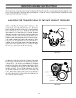
ADJUSTING THE TRANSFER ROLL TO DIE FACE CONTACT PRESSURE
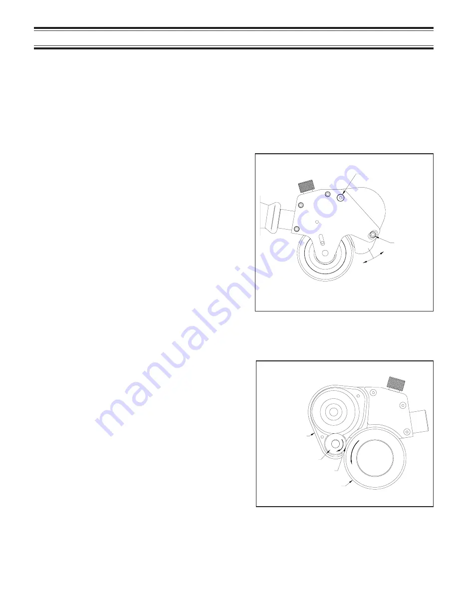
FIGURE 37
FIGURE 38
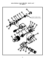
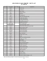
If for any reason, it becomes necessary to disassemble the entire printer, use the exploded parts diagram in the
back of this manual for reference during reassembly. There are only 2 critical assembly instructions which
require particular attention as follows:
When reinstalling the inking system housing on the
printer frame, first install Pivot Screw “A”. The Pivot
Screw should be snug but not tight. Install Adjusting
Screw “B” but leave it loose. With the Transfer Roll
fully seated on it’s axle and the Print Drum properly
installed, pivot the Inking System Housing towards the
print drum until the surface of the Transfer Roll makes
positive contact with the Bearer rings on the Print Drum.
The contact pressure should be just enough to posi-
tively drive the Transfer Roll when the Print Drum is
rotated. When the proper position has been reached,
tighten Screw “B” and then Screw “A”. Rotate the Print
Drum to ensure the Transfer Roll is rotating.
In operation, when the Print Drum is rotating, the rubber
Bearer rings on the Print Drum must positively drive the
Transfer Roll. The amount of engagement pressure
exerted at the contact point between these two compo-
nents is adjustable by moving the position of the Inking
System Housing. If the contact pressure is too light,
the Transfer Roll will not rotate and no ink transfer will
occur. If the contact pressure is excessive, it will cause
too much drag on the Print Drum and the Index Mecha-
nism will not operate properly.
ADJUSTING
SCREW “B”
PIVOT SCREW “A”
ADJUST FOR
LIGHT CONTACT
INKING SYSTEM
HOUSING
TRANSFER ROLL
CONTACT POINT
BEARER RING
CODER REASSEMBLY INSTRUCTIONS
Содержание HPNP-100
Страница 25: ...25 ...


