(3)
Construction and Handling
2.1 Fuel System
♦
Fuel system
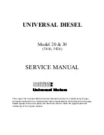
The fuel system schematic is shown in Fig. 1 with the fuel
flowing in the direction indicated by the arrows. To bleed air
from the system, loosen the vent plug “A” on the fuel filter
and crank the engine until there are no more air bubbles from
the vent. Tighten vent A’ and purge the air from the injection
pump at vent “B” using the same procedures.
a) Fuel
tank
b) Fuel
cock
c) Fuel
filter
d) Fuel
injection
pump
e) Injection
pipe
f) Nozzle
holder
g) Overflow
pipe
A. Vent
plug,
filter
B. Vent
plug,
pump
Fig 1. Fuel System
♦
Fuel-filter
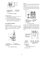
The fuel filter is of the cartridge type shown schematically in
Fig. 2. Under normal conditions it should only have to be
replaced every 400 hours. To install, apply a small amount of
fuel to the packing and tighten securely by hand. For
removal, the use of a filter wrench 15221—86611 is
recommended.
1. Fuel
Filter
2. Cover
3. Pipe
coupling
4. Vent
plug
5. “O”
ring
6. “O”
ring
7. Element
Fig. 2. Fuel Filter
♦
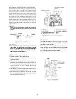
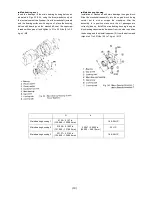
Fuel injection timing
Fuel injection timing is adjusted by changing the number of
shims used between the pump and the gear case it fits into.
See Fig. 3. One shim corresponds to approximately 1.5
degrees in crank angle. Therefore, injection will take place
1.5 degrees later when a shim is added and 1.5 degrees
earlier when a shim is removed. The timing is correct when
the pointer in the peephole on the side of the flywheel
housing lines up with the “F 1” marked on the flywheel. See
Fig. 4.
Fig. 3. Adjustment of Fig. 4. Inspection of
Injection Timing Injection Timing
Содержание Universal diesel 5416
Страница 21: ...19...

