


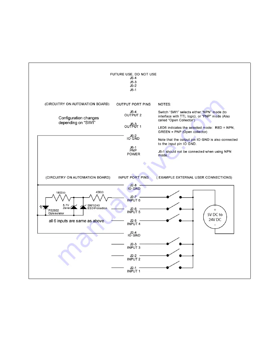
External Wiring
The automation kit connector J2 is used to wire external signals to six programmable inputs which can initiate
various laser functions. To trigger a function, supply between 5V DC to 24V DC to one of the input pins as
shown below. It is not necessary to limit current with a resistor to the input pins. The pulse on the input pins
should be held high longer than 5mS in order to register.
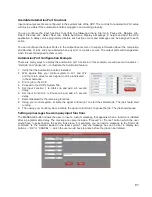
Automation Kit I/O Connections
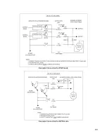
The automation kit connector J6 is used to poll the two programmable status outputs. It can be used in two
modes, selectable by the “PNP/NPN” switch on the top of the board. LED 5 indicates the position of this
switch, lighting up green for PNP or red for NPN mode. Two example diagrams are shown below to indicate
the difference between the modes. PNP (also known by the name “open-collector”) mode is recommended in
most cases. In both modes, the user must supply correct value resistors to limit the current to 25mA or less.
The voltage used should not exceed 32V DC.
79
Содержание VLS2.30
Страница 1: ...VLS Desktop User Guide VLS2 30 VLS3 50 www ulsinc com Revision 2012 08...
Страница 5: ...Chapter 1 Specifications 5...
Страница 8: ...Chapter 2 Safety 8...
Страница 9: ......
Страница 15: ......
Страница 16: ......
Страница 19: ...Chapter 3 Installation 19...
Страница 36: ...Chapter 4 Operation 36...
Страница 62: ......
Страница 68: ...Chapter 5 Accessories 68...
Страница 80: ...Example Connection for PNP mode Example Connection for NPN mode 80...
Страница 92: ...Chapter 6 Maintenance 92...
Страница 99: ...www ulsinc com...


