Universal Laser Systems VLS2.30 Скачать руководство пользователя страница 52

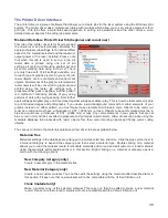
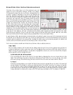
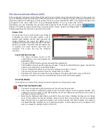
Image Enhancement Dropdown Menu 

Various  Image  Enhancement  modes  improve  marking  and  engraving  quality  at  high  speed  by 
compensating  for  laser  response  in  order  to  make  edges  crisp  and  defined  and  to  keep  thin 
elements of a graphic being printed, such as certain fonts (especially at small font sizes) and thin 
vertical  lines,  from  fading  out.  Four  Modes  are  available:  Disabled,  Manual,  Automatic  with 
margins, Automatic without margins.

Note:

 The Image Enhancement feature is not available in 3D or rubberstamp printing modes.

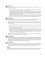
Automatic Enhancements With Margins (Drop Down Menu)

Calculates optimal enhancements but with margins on either side of the printing for best edge 
quality. With margins added the motion system over-strokes (travels beyond the edge of the print 
data) so that the motion system does not try to laser mark or engrave while it is accelerating or 
decelerating to change direction for the next raster stroke. If engraving or marking near the edges 
of the laser processing field these margins are automatically reduced.

Automatic Enhancements Without Margins (Drop Down Menu)

Decreases file completion times by removing over stroke margins. The laser system attempts to 
compensate for laser response while accelerating or decelerating to change directions for the 
next raster stroke but edge quality may suffer on some materials.

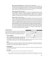
Image Enhancement Manual Mode

In manual mode Image Enhancement controls (CONTRAST, DEFINITION and DENSITY) can be 
adjusted manual. Keep in mind that the TUNING value may need to be readjusted for different 
settings of the manual image enhancements. Manual mode settings are explained here:
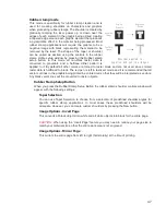
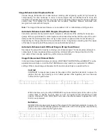
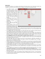
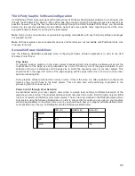
Contrast

CONTRAST increases laser power at the edges of thin graphical elements in areas of a 
graphic  that  are  high  density  (a  lot  of  detail  packed  close  together)  such  as  the  area 
outlined in the figure below:

Within this area, using too little CONTRAST may cause thinner parts of the letters or thin 
vertical  lines  to  appear  too  thin,  faint  or  even  non-existent  when  Rastering  at  high 
speeds. Having too much CONTRAST will cause the affected areas to appear too thick, 
bold or over-powered.
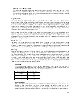
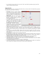
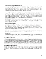
De

fi

nition

DEFINITION increases laser power at the edges of thin graphical elements in areas of a 
graphic that are lower density (graphic elements with a lot of white space around them) 
such as the area outlined in the figure below:

52

U n i v e r s a l  L a s e r  S y s t e m s  I n c .

U n i v e r s a l  L a s e r  S y s t e m s  I n c .

Содержание VLS2.30

Страница 1: ...VLS Desktop User Guide VLS2 30 VLS3 50 www ulsinc com Revision 2012 08...

Страница 2: ...Universal Laser Systems Inc All other company and product names are trademarks or registered trademarks of their respective companies Universal s laser systems are protected under one or more of U S P...

Страница 3: ...988 Universal Laser Systems has been committed to continually improving our technology and customer driven laser solutions Your satisfaction is very important to us and we welcome your feedback Tell u...

Страница 4: ...ce Guide contains the Software Installation CD Please follow the instructions for proper installation Warranty Your Reference Guide contains Warranty documents pertaining to your purchase Should you r...

Страница 5: ...Chapter 1 Specifications 5...

Страница 6: ...spike protected Particulate Odor Outside Ventilated Exhaust System High pressure vacuum blower capable of 150 CFM cubic feet per minute 6 inches static pressure 255m3 hr at 1 5kPa 250 CFM cubic feet...

Страница 7: ...port only Laser Options 10 25 and 30 watts 10 25 30 40 and 50 watts Power Consumption up to 110V 10A 240V 5A Overall Dimentions WxHxD With Cart 26 x 44 x 25 in 661 x 1118 x 635 mm Without Cart 26 x 1...

Страница 8: ...Chapter 2 Safety 8...

Страница 9: ......

Страница 10: ...ctrum For your protection the laser is contained within a Class 1 enclosure designed to completely contain the CO2 laser beam CAUTION Use of controls or adjustments or performance of procedures other...

Страница 11: ...ntense light that appears during the engraving or cutting process is the product of material combustion or vaporization DO NOT STARE AT THIS INTENSE LIGHT FOR LONG PERIODS OF TIME OR VIEW DIRECTLY WIT...

Страница 12: ...on Emission Warning Device A visible warning light that indicates when the laser is capable of emitting laser radiation 4 Attenuator A mechanical device to block emission of laser radiation This devic...

Страница 13: ...special eyewear and clothing and regular inspection of all safety measures surrounding the controlled area in which a Class 4 laser system is operated The LSO may be required to maintain records as ne...

Страница 14: ...abels CDRH and CE regulations require that all laser manufacturers affix warning labels in specific locations throughout the equipment The following warning labels are placed on the laser system for y...

Страница 15: ......

Страница 16: ......

Страница 17: ...tive 2002 96 ECC WEEE Directive based on the standards listed Standards Used Safety EN 60950 2002 EN 60825 1 2007 Class 2 EMC EN 55024 1998 Class A EN 55022 2003 Class A EN 61000 3 2 2001 class A EN 6...

Страница 18: ...ions Operation of this equipment in a residential area is likely to cause harmful interference in which case the user will be required to correct the interference at his or her own expense Users shoul...

Страница 19: ...Chapter 3 Installation 19...

Страница 20: ...resent in a confined unventilated room can create a health hazard 4 For best results since the laser cartridges are air cooled we recommend operating the laser system between the ambient temperatures...

Страница 21: ...n exhaust gate to adjust airflow and to close off the exhaust when the laser is not in use Place this gate near the laser system within 5 to 10 feet 1 50 to 3 00 meters 7 Use a short piece of industri...

Страница 22: ...wer inlet User Supplied 4 Shut off or air flow gate User Supplied 5 Adapter to the hose reduces from 4 to 3 User Supplied 6 Flexible wire reinforced industrial grade rubber hose User Supplied 7 Connec...

Страница 23: ...dows 7 2 GB of RAM minimum 40 GB hard drive 15 GB free space minimum VGA monitor minimum 1024 x 768 resolution CD DVD Drive Mouse and keyboard Available USB 2 0 Hi Speed compliant port only Computer s...

Страница 24: ...settings can be controlled through the power options in the Windows control panel on your PC The illustrations below show you how to disable power management XP Vista and 7 For the Power Scheme in use...

Страница 25: ...you are installing software Note If the setup window does not automatically launch you can launch it manually Locate your CD or DVD drive using Windows Explorer and launch the Setup exe application to...

Страница 26: ...laser system until the final step Checking Beam Alignment Exhaust Air Filtration Unit Assembly Optional 1 Unpack the air filtration unit and place it on a level surface 2 Push down on the tabs of the...

Страница 27: ...f the two Serial ports 2 of the laser system and the Serial port connector on the air filtration unit 3 Secure the Serial cable using the retainer clips 4 8 Attach a power cord to the laser system s p...

Страница 28: ...system The laser system will not function without a charged battery installed Keep a spare 9 volt battery on hand at all times 4 In some instances the laser must be installed in the laser system If th...

Страница 29: ...wn with arrows below and the laser connector on the left side of the laser compartment c Locate the V groove along the upper 3 and lower 2 part of the laser cartridge base plate and the alignment plat...

Страница 30: ...k cover 5 Plug the laser system an optional exhaust air filtration unit if present into appropriate power outlets 6 Connect the USB cable provided with the laser system between the USB port of the com...

Страница 31: ...t this time Then select Next to continue a Select Install the software automatically Then Select Next to continue You do not need to insert the Software Installation CD ROM b Select Finish to close th...

Страница 32: ...ser system keypad 5 With the top door open a red target pointer will appear on the masking tape 3 The red target pointer should appear centered within 1 8 inch 3 mm If not turn off the laser system re...

Страница 33: ...at support ulsinc com Note This example uses CorelDRAW and the CorelDRAW sample file provided on the installation CD The file is also provided in eps or dxf for use in other applications if CorelDRAW...

Страница 34: ...dized Figure 5 4 Set the Fixture Type to NONE Note If you were using an optional accessory or custom fixture you would choose it from the fixture list 5 Measure the thickness of the material a digital...

Страница 35: ...ry If you cannot resolve the issue please contact your distributor or the ULS Customer Service Department Never leave the laser system unattended while laser processing Step 5 Material Removal and Rel...

Страница 36: ...Chapter 4 Operation 36...

Страница 37: ...into a material by etching a pattern of dots into the material at high resolutions up to 1000 dpi and a vector mode in which the laser follows a two dimensional path to cut or mark a shape into a mat...

Страница 38: ...phs If you desire a solid background removal for certain elements of your graphic instead of a dither pattern you must make those elements solid black in color Objects to be vector cut must be in red...

Страница 39: ...rmal for most materials and application or one of the other modes for special applications The modes work as follows Normal mode In this mode all raster data is converted to grayscale and then a dithe...

Страница 40: ...ntages to process rasters from the bottom up to prevent smoke from marring the previously marked or engraved surfaces Vector performance This setting allows you to adjust vector performance from Stand...

Страница 41: ...terial this switch is set To restore materials that are disabled hidden Press CRTL F2 Fiber CO2 laser support Select one or more of the lasers offered by ULS the laser must be compatible with your par...

Страница 42: ...imit the material thickness values that can be entered at time of printing The more thicknesses you enter laser settings for the more accurately the materials database can calculate the settings for o...

Страница 43: ...o the manual tab When you do this the settings stored in the materials database for the material selected will be transferred to the manual tab including the laser power and processing speeds for rast...

Страница 44: ...ring on the edges when cutting Lower PPI settings may reduce this effect but may result in a serrated looking edge Using less than 150 PPI may result in the pulses being spread so far apart that they...

Страница 45: ...abort these changes by selecting Cancel selecting OK or APPLY will approve the changes Save Button The save button brings up a dialog box which allows you to save a snapshot of the laser job settings...

Страница 46: ...get the desired results By default all other colors are forced to raster mode and are not used since colored raster data is converted to grayscale The red pen is left in rast vect mode and it is recom...

Страница 47: ...t is recommended that all vector cut lines in the graphic being printed be colored red so that they will be interpreted as vectors Any black vector lines will the converted to raster objects Rubber St...

Страница 48: ...and the black color job settings are used for processing Because of this you will notice that the color table is reduced to one color black when this mode is selected The dither pattern applied is th...

Страница 49: ...me materials you may get better results by starting at the bottom and engraving towards the top of the field Up due to the fact that smoke and fumes from the engraving process travel over the surface...

Страница 50: ...omputer using a grayscale scanner setting Ideally the scanned image of text should be black text on a white background but if a grayscale scanner setting was used there may be very light gray pixels a...

Страница 51: ...e is optimized for the particular raster speed and power level stored in the database If you need to change the speed or power significantly for your application you may need to determine a new value...

Страница 52: ...moving over stroke margins The laser system attempts to compensate for laser response while accelerating or decelerating to change directions for the next raster stroke but edge quality may suffer on...

Страница 53: ...work best when you are not overpowering the material The first step is to establish the minimum laser power necessary at the desired processing speed to mark the material or to engrave the material to...

Страница 54: ...e density to 1 draft mode Make sure you set your processing speed equal to the speed at which you plan to run your application and the laser power set high enough to mark the material This will result...

Страница 55: ...types of vectors Processing speed for these types of vectors is controlled by other rules in the software This control allows you some adjustment of processing speed of curves and small line segments...

Страница 56: ...is useful if you need to load new material in between each page Rotary A rotary fixture option is available for all models Please contact Universal Laser System for more details Diameter If a rotary f...

Страница 57: ...laser system are duplicated here The green START button begins processing the selected job The PAUSE button stops the engraving process Pressing the PAUSE button again resumes the engraving process w...

Страница 58: ...for that anchor point in the X Y fields to the right of the preview screen Using the X Y manual motion buttons you can move the focus carriage to a location on the processing table in the laser syste...

Страница 59: ...er computers using the proprietary ULS job format file extension EMF deleting print jobs marking jobs as permanent so they will not be deleted by the FIFO systems purging the entire queue except for j...

Страница 60: ...eature and follow the instructions given The ALIGNMENT Mode Launch button opens the Alignment Mode window for checking and adjusting alignment of the laser to the motion system The Alignment feature s...

Страница 61: ...is indicates that the laser cartridge is either not functioning properly or is disabled because one of the safety interlocked doors to the laser system is open causing the interlock system to disable...

Страница 62: ......

Страница 63: ...raphics to your material A third method is to use fixturing to position your material This is especially useful for odd shaped materials The laser system can even be used to create the fixturing For e...

Страница 64: ...ote Make sure the lens specified in the system tab of the UCP matches the lens installed in the laser system when using this feature and that the Auto Z function is enabled CAUTION In order for this m...

Страница 65: ...age size and orientation As a rule of thumb try to set the page orientation in your software of choice to Landscape and the page size to match the engraving area of your laser system This should resul...

Страница 66: ...ages for laser processing using variable spacing between the dots to create the illusion of shades of gray These dither patterns are relatively coarse so it is not necessary to use high resolution bit...

Страница 67: ...ystem is a 2D device so you must create a 2D drawing view of the object you want to laser process You cannot print 3D parts and assemblies directly to the laser system To control placement of your job...

Страница 68: ...Chapter 5 Accessories 68...

Страница 69: ...n be provided by the ULS Computer Controlled Compressed Air Unit The Air Assist System consists of a backsweep or a cone fitting and an ULS Computer Controlled Compressed Air Unit The backsweep fittin...

Страница 70: ...focus on the material to be processed and then align the nozzle using the angle and height adjustments toward the red target laser which is on when the laser system is powered on and the top door is o...

Страница 71: ...to the cone base and running the laser system without airflow will cause smoke from laser processing to be drawn up into the cone and rapidly damage the focus lens Installation 1 Remove if present the...

Страница 72: ...It is best to start with the needle valve at maximum flow turn the needle valve counterclockwise until it seats then adjust as necessary Removal Loosen the thumbscrew and pull the Cone downwards Leave...

Страница 73: ...ed for maintenance as a whole Installation 1 Insert one end of the provided blue coil hose into the air supply fitting on the back of the laser system 2 Then connect the other end of the blue coil hos...

Страница 74: ...laser system To reduce noise and prolong filter life the filtration unit only operates while the laser system is running a job The filtration unit has sensors to monitor the pre and HEPA filters and...

Страница 75: ...the material from laser back reflection which can occur when the laser reflects off of the table supporting the material if you attempt to cut without the cutting table Installation 1 Turn on your las...

Страница 76: ...owever if the zero position does not appear to be correct you may need to recalibrate the table See the calibration instructions below Cutting Table Focus Lens Calibration To properly use the cutting...

Страница 77: ...o scribe and or etch some uncoated metals such as stainless steel directly without the assistance of chemicals or coatings The HPDFO replaces the standard lens kit in the carriage and comes with its o...

Страница 78: ...es via the Automation Kit Outputs are intended to be used for informational purposes such as to indicate error conditions they are not intended to drive external devices Installation 1 Insure power is...

Страница 79: ...ister Automation Kit I O Connections The automation kit connector J6 is used to poll the two programmable status outputs It can be used in two modes selectable by the PNP NPN switch on the top of the...

Страница 80: ...Example Connection for PNP mode Example Connection for NPN mode 80...

Страница 81: ...feature 1 Verify that the Automation board is installed 2 Wire signals from your control system to J2 1 and J2 2 and the return wires for each signal to J2 4 as indicated in the schematics 3 Print a j...

Страница 82: ...Service Team at 480 609 0297 USA 43 1 402 22 50 Austria 81 45 224 2270 Japan or e mail us at support ulsinc com Installation 1 Remove the engraving table by loosening the two captive thumbscrews 1 an...

Страница 83: ...and center red alignment pointer on the right alignment pin c Next select the System Tab and press the Rotary CALIBRATE button to activate the Rotary Calibration Window Press the Y position SAVE butto...

Страница 84: ...recessed slot and adjust until the connector engages the alignment pins protrude through the alignment holes in the base of the rotary fixture and the rotary is sitting flat The rotary will indicate...

Страница 85: ...one fixture Use the focus tool and manually focus on top of the flat part of the internal cone fixture b Next select the System Tab and press the Rotary CALIBRATE button to activate the Rotary Calibra...

Страница 86: ...entered inside of the inverted cone Push the adjustable end of the fixture 3 to the right firmly against the bottom of the material Lower the lever on the end of the fixture to lock the material in pl...

Страница 87: ...e the center of your graphic is facing directly up Keep in mind that the rotary fixture does not have a home location in the rotational axis so the top most part of the material the part facing straig...

Страница 88: ...t select print in your graphics software and check to make sure rotary mode is still enabled and the correct diameter for your material is still entered in the printer driver dialog 12 Then set the ap...

Страница 89: ...dialog In the materials driver tab select the material you are going to laser process select Rotary in ther fixture section and enter the diameter of the material measured earlier 4 Finally printing...

Страница 90: ...th support and stop pins 4 Place material to be processed on pins 5 Focus on top of material surface Direct Import software accessory Direct Import is a software add on that allows you to import PDF a...

Страница 91: ...gs assigned to each color DXF import process ignores image density manual controls and preserves vector data at the highest resolution PDF import supports both raster and vector data When using the ma...

Страница 92: ...Chapter 6 Maintenance 92...

Страница 93: ...for visibility 93 1 Focus carriage 2 X Axis bearing 4 3 3 mirror inside cover plate 4 Focus lens inside cover plate 5 X Axis rail arm 6 X Axis bearing track 2 7 X Axis belt 8 X Axis idler pulley 9 2 m...

Страница 94: ...the inside of the device Clean the processing table surface with either a soap solution or alcohol and a cloth or paper towels acetone can be used in extreme cases to remove gummy deposits but should...

Страница 95: ...visual inspection of the 2 and 3 mirrors beam window and focus lens should be performed at least once a day CAUTION Do not clean an optic that appears clean Excessive cleaning can damage the optical...

Страница 96: ...peat the procedure Reinstall the mirror by sliding it back into its holder until seated CAUTION When reinstalling the mirror make sure not to install it backwards 3 Mirror and Focus Lens Loosen the tw...

Страница 97: ...lling Exhaust Plenum The exhaust plenum should be routinely inspected and cleaned to ensure good exhaust flow To access the inside of the exhaust plenum lower the engraving table to the bottom of its...

Страница 98: ...for debris Clean ONLY if dirty Every month Clean cooling fan filters Clean Z Axis lead screws with white lithium grease Check for X Axis and Y Axis belt wear Replace as necessary Check and or clean X...

Страница 99: ...www ulsinc com...

Отзывы: