background image

EX-RC1   

R e m o t e   I / O   Ad a p t e r

2/12

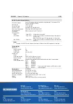
EX-RC1 Technical Specifications 

I/O module capacity 

Up to 8 I/O modules can be connected to a single adapter. The number of I/Os 
may vary according to module. 

Power supply 

12VDC or 24VDC  

Permissible range 

10.2 to 28.8VDC 

Quiescent current 

90mA@12VDC; 50mA@24VDC 

Max. current consumption 

650mA @ 12VDC; 350mA @ 24VDC 

Current supply for  
I/O modules 

800mA maximum from 5V. See Note 1 

Status indicators 

(PWR) 

Green LED—  Lit when power is supplied. 

(I/O COMM.) 

Green LED—  Lit when communication is established between the adapter to 

the other units. 
Blinks 0.5sec ON 0.5sec OFF when adapter is in Stop mode. 

(Bus COMM.) 

Green LED—  Lit when communication is established between the adapter and 

the OPLC. 

Notes

1.

 Example: 2 IO-DI8-TO8 units consume a maximum of 140mA of the 5VDC supplied by the adapter.

Communication

RS232 port 

Galvanic isolation 

No 

Voltage limits 

±

20V 

Cable length 

Up to 15m (50‘) 

CANbus port 

Nodes

60

Power requirements 

24VDC (±4%), 40mA max. per unit 

Galvanic isolation 

Yes, between CANbus and adapter 

Cable type 

Twisted-pair; DeviceNet® thick shielded twisted pair cable is recommended. 

Cable length/baud rate 

25 m 
100 m 
250 m 
500 m 
500 m 
1000 m* 
1000 m* 

1 Mbit/s  
500 Kbit/s 
250 Kbit/s  
125 Kbit/s  
100 Kbit/s  
50 Kbit/s  
20 Kbit/s 

* If you require cable lengths over 500 meters, contact

technical support.

Environmental

IP20/NEMA1 

Operating temperature 

0

°

to 50

°

C (32 to 122

°

F) 

Storage temperature 

-20

°

to 60

°

C (-4 to 140

°

F) 

Relative Humidity (RH) 

5% to 95% (non-condensing) 

Dimensions (WxHxD) 

80mm x 93mm x 60mm (3.15” x 3.66” x 2.36”) 

Weight

135g 

(4.76 oz.)

Mounting 

Either onto a 35mm DIN-rail or screw-mounted. 

Samara

tel. +7 846 273 95 85

[email protected]

Yekaterinburg

tel. +7 343 287 19 19

[email protected]

St. Petersburg

tel. +7 812 327 3752

[email protected]

Moscow

tel. +7 495 641 1616

[email protected]

Helsinki

tel. +358 9 540 4940

[email protected]

Vilnius

tel. +370 5 215 1646

[email protected]

Riga

tel. +371 6738 1617

[email protected]

Мinsk

tel. +375 17 200 0876

[email protected]

Tallinn

tel. +372 668 4500

[email protected]

Кiev

tel. +38 044 495 33 40

[email protected]

Содержание EX-RC1

Страница 1: ...understand this document and any accompanying documentation All examples and diagrams shown herein are intended to aid understanding and do not guarantee operation Unitronics accepts no responsibility for actual use of this product based on these examples Please dispose of this product in accordance with local and national standards and regulations Only qualified service personnel should open this...

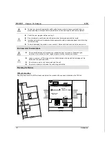
Страница 2: ...sconnect the device when the power is on Environmental Considerations Do not install in areas with excessive or conductive dust corrosive or flammable gas moisture or rain excessive heat regular impact shocks or excessive vibration Leave a minimum of 10mm space for ventilation between the top and bottom edges of the device and the enclosure walls Do not place in water or let water leak onto the un...

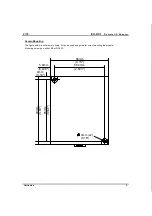
Страница 3: ...tronics 3 Screw Mounting The figure below is not drawn to scale It may be used as a guide for screw mounting the module Mounting screw type either M3 or NC6 32 4mm 5 8mm 0 228 85mm 3 346 80mm 3 15 68 4mm 2 693 93mm 3 66 4mm x2 0 16 0 16 ...

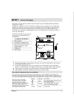
Страница 4: ...otective cap provided with the adapter This cap covers the port of the final I O module in the system To avoid damaging the system do not connect or disconnect the device when the power is on 1 2 Component identification 1 Module to module connector 2 Protective cap Wiring Do not touch live wires Unused pins should not be connected Ignoring this directive may damage the device Double check all wir...

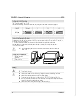
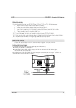
Страница 5: ... kgf cm Do not use tin solder or any other substance on stripped wire that might cause the wire strand to break Install at maximum distance from high voltage cables and power equipment Wiring Power Supply Connect the positive cable to the V terminal and the negative to the 0V terminal Earthing the Power Supply To maximize system performance avoid electromagnetic interference by Mounting the module...

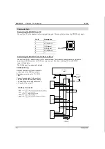
Страница 6: ...communicates via Unitronics proprietary UniCAN protocol UniCAN can comprise up to 60 nodes including PLCs and EX RC1 remote I O adapters The CANbus port is galvanically isolated CANbus Wiring 121 terminating resistor 121 terminating resistor Circuit protection device 24V Power Supply V L H V PE V L H V PE V L H V PE Network terminators Place terminators at each end of the CANbus network Resistance...

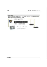
Страница 7: ...1 Remote I O Adapter Unitronics 7 Network Layout The EX RC1 enables you to remotely locate I Os up to 1 kilometer from a PLC You can include both PLCs and adapters on the UniCAN network up to a total of 60 nodes ...

Страница 8: ...per unit Galvanic isolation Yes between CANbus and adapter Cable type Twisted pair DeviceNet thick shielded twisted pair cable is recommended Cable length baud rate 25 m 100 m 250 m 500 m 500 m 1000 m 1000 m 1 Mbit s 500 Kbit s 250 Kbit s 125 Kbit s 100 Kbit s 50 Kbit s 20 Kbit s If you require cable lengths over 500 meters contact technical support Environmental IP20 NEMA1 Operating temperature 0...

Отзывы: