
2/12
EX-RC1
R e m o t e I / O Ad a p t e r
Unitronics
3
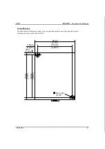
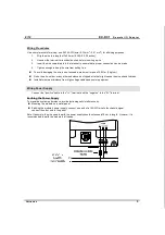
Screw-Mounting
The figure below is not drawn to scale. It may be used as a guide for screw-mounting the module.
Mounting screw type: either M3 or NC6-32.
4mm
5.8mm
(0.228")
8
5m
m
(3
.3
4
6"
)
80mm
(3.15")
68.4mm
(2.693")
9
3m
m
(3
.6
6")
4mm (x2)
(0.16")
(0.16")


