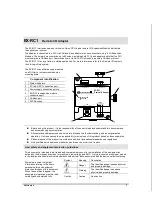

EX-RC1
R e m o t e I / O Ad a p t e r
2/12
2
Unitronics
Failure to comply with appropriate safety guidelines can result in severe personal injury or
property damage. Always exercise proper caution when working with electrical equipment.
Check the user program before running it.
Do not attempt to use this device with parameters that exceed permissible levels.
Install an external circuit breaker and take appropriate safety measures against short-circuiting
in external wiring.
To avoid damaging the system, do not connect / disconnect the device when the power is on.
Environmental Considerations
Do not install in areas with: excessive or conductive dust, corrosive or flammable gas,
moisture or rain, excessive heat, regular impact shocks or excessive vibration.
Leave a minimum of 10mm space for ventilation between the top and bottom edges of the
device and the enclosure walls.
Do not place in water or let water leak onto the unit.
Do not allow debris to fall inside the unit during installation.
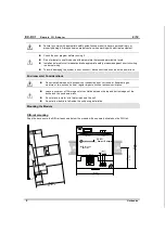
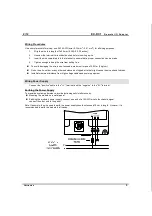
Mounting the Module
DIN-rail mounting
Snap the device onto the DIN rail as shown below; the module will be squarely situated on the DIN rail.
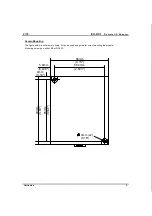
93
m
m
(3
.6
6"
)
4
4.
5
m
m
(1
.7
5"
)
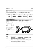
POWER
EX-RC1
0V
V
Remote I/O Adapter
PRG
Network ID
CANbus
PWR
I/O COMM.
Bus COMM.


