
EX-RC1
R e m o t e I / O Ad a p t e r
2/12
4
Unitronics
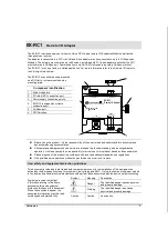
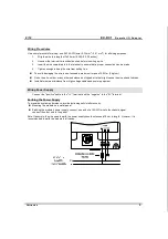
Setting the Unit ID Number
The ID number range is from 1 to 60.
The DIP switch settings represent the ID number as a binary value as shown in the following figures.
Unit ID
1 (Default)
2
59
60
Settings
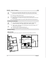
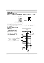
Connecting Expansion Modules
An adapter provides the interface between the OPLC and an expansion module. To connect the I/O module to
the adapter or to another module:
1.
Push the module-to-module connector into the port located on the right side of the device.
Note that there is a protective cap provided with the adapter. This cap covers the port of the final
I/O module in the system.
To avoid damaging the system, do not connect or disconnect the device when the
power is on.
1
2
Component identification
1
Module-to-module
connector
2
Protective cap
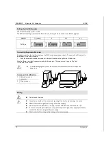
Wiring
Do not touch live wires.
Unused pins should not be connected. Ignoring this directive may damage the device.
Double-check all wiring before turning on the power supply.
Do not connect the ‘Neutral or ‘Line’ signal of the 110/220VAC to the device’s 0V pin.
In the event of voltage fluctuations or non-conformity to voltage power supply specifications,
connect the device to a regulated power supply.
Double-check all the wiring before turning on the power supply.


