background image

Installation, Operation and Maintenance Manual

Marvel Plus

21

Subject to change without notice.

120.5-IM (1018)

U01 

Sensor Setup

Liquid Pressure 1

 Calibration  > 

00psi 


Actual > 

136psi 


4ma > 

003psi 


20ma > 

664psi

U01 

Sensor Setup

VFD Frequency

 Calibration  > 

00.0Hz 


Actual > 

08.4Hz 


0ma > 

00.0Hz 


20ma > 

60.0Hz

U01 

Sensor Filters

AI1 >  07 

AI2 >  OFF 

AI3 >  07 

AI4 >  07 

AI5 >  07

U01 

Sensor Setup

VFD

Action Direct 

Minimum 00.0vdc 

Maximum 10.0vdc

U01 

Sensor Setup

VFD

Action Direct 

Minimum 00.0vdc 

Maximum 10.0vdc

U01 

Sensor Setup

Dig Cmpr1

Action Direct 

Minimum 00.0vdc 

Maximum 10.0vdc

U01 

Sensor Setup

Dig Cmpr2

Action Direct 

Minimum 00.0vdc 

Maximum 10.0vdc

U01 

Sensor Setup

DPC Valve

Action Direct 

Minimum 00.0vdc 

Maximum 10.0vdc

Содержание Marvel Plus

Страница 1: ...Marvel Plus MICROPROCESSOR CONTROLLER Installation Operation and Maintenance Manual Effective October 2018 Interactive PDF DISCONTINUED For Reference Only ...

Страница 2: ...essor Minimum On Status Screen 11 Compressor Minimum Off Status Screen 11 Analog Outputs Status Screen 11 Occupied Unoccupied Override Screen 11 Menu and Sub Menu Areas 12 Enables 12 System Enables 12 Constant or Variable Air Flow Enables 12 Set Points 12 Set Points continued 13 Cooling Mode 13 Heating Mode 13 Set Points continued 14 Morning Warm up 14 Warm Up Set Points 14 Morning Cool Down 14 Co...

Страница 3: ...ndicates a potentially hazardous situation which may result in minor or moderate injury if not avoided The information icon indicates a situation that may result in equipment or property damage The information provided alerts the reader to relevant facts and or conditions ELECTRICAL HAZARD WARNING CAUTION INFORMATION This publication includes warnings cautions and information icons that point out ...

Страница 4: ...em schedules alarm set points and alarm history are stored in non volatile memory Each Marvel Plus controller has the ability to record up to 50 alarms faults under an alarm history page to allow technicians to scroll through alarm history to view critical operating data temperatures and optional discharge refrigerant pressure units with head pressure control option at the time of failure The Marv...

Страница 5: ...an alarm condition the button illuminates a continuous Red Depending on the type of alarm the system may shut down or continue to operate Some alarms are just simple faults known as indicators which are not harmful to the operation of the unit but may require attention in the near future Pressing the button will reveal what alarm caused the system to shut down To reset an alarm press the button un...

Страница 6: ...ing cool down set points Return Air Temperature Control Option If the application requires both cooling and heating or requires humidification or dehumidification a return air sensor is factory provided but must be field installed The return air sensor will be used to determine the mode of operation Cooling Heating Humidification Dehumidification and or Reheat Sequence of Operation After power is ...

Страница 7: ...he quantity of heaters for Reheat Mode is determined by the heating demand based on return air temperature Air Side Economizer Option If the system has the Airside Economizer Option the system will utilize the airside economizer when the outdoor air enthalpy is less than return air enthalpy and the outdoor air temperature is less than the outdoor air temperature set point minus the Band set point ...

Страница 8: ...strain relief facing downward 4 Drill a 1 2 hole through the face of the duct 5 Before installing the duct pressure transducer make sure the gasket at the base where the duct probe meets the transducer housing is intact and sealed to the sensor so that it will seal the perimeter of the hole drilled 6 Insert the probe into the duct and mount the pressure transducer using two 2 field provided 8 shee...

Страница 9: ...r function within the system The screens are only representative of the possible combinations of functions and will change depending on whether the various options are enabled System Status Home Screen U01 13 48 05 01 13 Return Hum 050 0 Return Temp 068 1 F Supply Temp 048 2 F Occupied System ON HEAT This screen shows the time and date return air humidity option return air temperature supply air t...

Страница 10: ...ows the amount of demand for cooling heating humidification dehumidification and reheat The status of cooling heating humidification dehumidification and reheat shown on the screen is the amount of cooling heating required to meet the set point required Water Status Screen U01 Water Water Pump ON Temperature 40 8 F Water Econ Dem 000 This screen shows the status of the water pump option and the re...

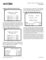
Страница 11: ...Screen U01 Analog Outputs VFD Blower 07 6vdc DPC Valve 03 5vdc Heating 00 0vdc WSE Valve 06 5vdc This screen shows the output status of the VFD Blower the DPC Discharge Pressure Control valve Modulated Heaters and the WSE waterside economizer valve Occupied Unoccupied Override Screen U01 Thursday 08 34 May 02 2013 OVERRIDE MODE Mode THU OCCUPIED Override Status OFF Override Time 2hrs This screen s...

Страница 12: ...e main screen to turn the unit on or off and enable or disable the compressors To turn the unit on or off or to enable or disable a component on these screens press the button to relocate the cursor to the component to enable or disable Next press the or button one time to toggle the setting on or off then press the button again to initiate the change System Enables U01 System Enables Dehumidifica...

Страница 13: ...Mode Set Point and Band Return Air Humidity Setpoint 050 0 F Band 05 0 F Return Air Humidity is used to set the control points for optional dehumidification and humidification functions Setpoint is the setting for the humidity control to try to maintain Band is the setting used to adjust the on off points of the dehumidification mode or humidification mode If the system has humidification the humi...

Страница 14: ...ow the OA set point minus the OA band the outside air dampers are modulated open to maintain the cooling demand If the outdoor air temperature rises above the outdoor air temperature set point plus O A Band the outside air dampers are modulated closed or to the minimum damper position set point Air side economizer will be available as long as the out door air enthalpy is less than the return air e...

Страница 15: ...igh pressure switch that will lock out its particular compressor if the discharge pressure rises above the discharge pressure switches fixed trip point Alarm delay is the time delay allowed before the system will show up as a fault This is used as a means of allowing the system to recover before a fault is initiated U01 Return Temperature High Alarm 090 0 F Low Alarm 090 0 F Alarm Delay 120sec U01...

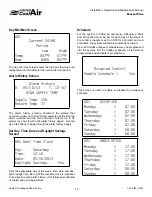
Страница 16: ...me 12 16 Date 05 10 2013 Daylight Savings Yes Sets the appropriate day of the week time date and day light savings time Set up of the real time clock is important to be able to record alarm history or for following scheduled occupied and unoccupied times Schedule For the system to follow an occupancy schedule a Start and End period must be set for each day of the week If the control schedule is se...

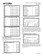
Страница 17: ...00 Wednesday 06 00 Thursday 06 00 Friday 06 00 Saturday 00 00 Sunday 00 00 MORNING WARMUP OFF Monday 06 30 Tuesday 06 30 Wednesday 06 30 Thursday 06 30 Friday 06 30 Saturday 00 00 Sunday 00 00 Unoccupied Temperature Control Screen U01 Unoccupied Control Temp Control ON High Temp 079 0 F Low Temp 062 0 F The unoccupied control screen sets the temperature swing that is allowed during the unoccupied ...

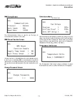
Страница 18: ...t would then be performed based on the reset communications points in the communication point list Change Password Screen U01 Change Passwords Level 1 0000 Technicians Menu Fan Delays Screen U01 Fan Delays Startup 005s Airflow Proof 030s Unit OFF Delay 10s The Fan Delays screen allows customer to set the amount of delay in seconds for system startup proof of air flow based on the amount of time it...

Страница 19: ...ual Dig In C1 High Press Auto C1 Low Press Auto C2 High Press Auto C2 Low Press Auto Morning Warmup Auto Airflow Auto U01 Manual Dig In WFDP AUTO C3 High Press Auto C3 Low Press Auto C4 High Press Auto C4 Low Press Auto Manual Dig In Filter AUTO Hi Heat Auto Freezestat Auto Fan Ovld 2 Auto U01 Manual Analog In VFD Input OFF 00 0Hz Static Pr OFF 0 0iwc Supply T OFF 000 0 F U01 Manual Analog In Wate...

Страница 20: ...the low end of a static pressure transducer is 0 0 w c and it starts at 4 mA then the start point would be 4 mA is 0 0 w c U01 Calibrate Sensor Return Temperature Calibration 000 0 F Actual 000 5 F U01 Calibrate Sensor Return Humidity Calibration 000 0 Actual 050 1 U01 Calibrate Sensor Supply Temperature Calibration 000 0 F Actual 054 5 F U01 Calibrate Sensor Ambient Temperature Calibration 000 0 ...

Страница 21: ...Hz Actual 08 4Hz 0ma 00 0Hz 20ma 60 0Hz U01 Sensor Filters AI1 07 AI2 OFF AI3 07 AI4 07 AI5 07 U01 Sensor Setup VFD Action Direct Minimum 00 0vdc Maximum 10 0vdc U01 Sensor Setup VFD Action Direct Minimum 00 0vdc Maximum 10 0vdc U01 Sensor Setup Dig Cmpr1 Action Direct Minimum 00 0vdc Maximum 10 0vdc U01 Sensor Setup Dig Cmpr2 Action Direct Minimum 00 0vdc Maximum 10 0vdc U01 Sensor Setup DPC Valv...

Страница 22: ...01 Digital Inputs Alarms ON Actual Filter OPEN CLOSE Hi Heat OPEN CLOSE Freeze OPEN CLOSE Fan Ovld2 OPEN CLOSE Alarm Logic Manual Reset Screen U01 Alarm Logic Manual Reset Fire Alarm NO The Alarm Logic Manual Reset allows each listed function to be set up as either automatic or manual reset type In either case the alarm still appears on the display screen Economizer Setup Screen U01 Economizer Typ...

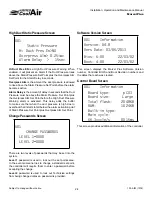
Страница 23: ...mizer Coils and Discharge Pressure Control Valves Setting a valve between greater than 1 will force the unit off and open the water valves to the specified set positions It is designed to flush the water lines Duct Static Pressure Screen U01 Static Pressure Rate 01s Step 003 Min 000 Max 100 Pressure Reset Yes Reset Offset 0 02iwc The Static Pressure screen is used to adjust the VFD control functio...

Страница 24: ...e is high due to overshoot that it starts to fall below the alarm activation point of Static Pressure Set Point plus Overpress Alm Set Point Change Passwords Screen U01 CHANGE PASSWORDS LEVEL 1 0000 LEVEL 2 0000 There are two levels of passwords that may be set into the system Level 1 password is used to lock out the set points area In the event someone tries to change a standard set point the con...

Страница 25: ...or All Indoor HVAC Projects Authorized Distributor LIMITED WARRANTY United CoolAir Units are backed by a 1 year limited warranty on parts and a 5 year limited warranty on the compressor labor not included Maintenance items such as filters and belts are excluded under this limited warranty FACTORY TESTED All units are functionally run tested before shipment to ensure a trouble free start up and uni...

Отзывы: