REF0717-2
11
Description
2
2.7 Chassis
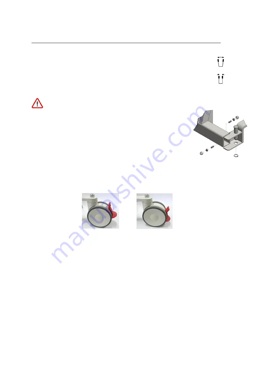
Both legs can be spread out to make room for obstacles e.g. a chair. The legs are electrically
adjustable by the buttons on the hand control. It’s advisable to transfer as much as possible with the
legs in the narrow position to prevent damage to the hoist or surrounding area.
2.7.1 Adjusting the legs of the Hoist
Make sure there is enough space to spread the legs. If the legs get stuck, this can damage the
hoist or its environment.
If parts of the leg adjustment need to be replaced, make sure that the legs are properly
adjusted. On the front and back of the frame next to the legs are set screws that remove
movement from the legs in the extreme positions. Loosen these set screws. Let the
motor run completely. Then adjust the legs perpendicular to the frame by turning the
M10 ball joints in or out of the frame. With the set screws you can remove the remaining
movement in both extreme positions. Do not over tighten!
This prevents problems with the motor or ball heads.
2.7.2 Wheels
The hoist has four swivel wheels, braked 100mm at the front and 125mm at the rear. The rear wheel brake
stops the wheel from rolling and the direction of rotation. Apply the brake using the tip of the foot. Always do
this with care.
The wheels have a very low rolling resistance due to the fully ball-bearing pivot points.
Moving the hoist from a standstill requires minimal force if the wheels of the chassis are already in line with
the direction of travel.


