035-17438-001 Rev. A (901)
Unitary Products Group
17
AIRFLOW
All CFM’s are shown at 0.5” w.c. external static pressure.
These units have variable speed motors that automatically
adjust to provide constant CFM from 0.0” to 0.6” w.c. static
pressure. From 0.6” to 1.0” static pressure, CFM is reduced
by 2% per 0.1” increase in static. Operation on duct systems
with greater than 1.0” w.c. external static pressure is not rec-
ommended.
At some settings, LOW COOL and/or LOW HEAT air flow
may be lower that what is required to operate an airflow
switch on certain models of electronic air cleaners. Consult
the instructions for the electronic air cleaner for further
details.
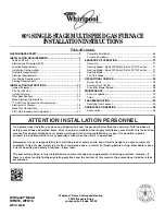
FIGURE 13 :
CFM Selection board
Table 6:
AIRFLOW DATA - MID EFFICIENCY 2 STAGE CFM/TAP SELECTION - VARIABLE SPEED
HIGH/LOW SPEED COOLING AND HEAT PUMP CFM
MODEL
JUMPER SETTINGS
P*DUA12V06401
G8V08012UHA11
L8V08012UHA11
P*DUB16V08001
G8V10016UHB11
L8V10016UHB11
P*DUC20V08001
G8V1002UHC11
L8V1002UHC11
P*DUC20V09601
G8V12020UHC11
L8V12020UHC11
COOL TAP
ADJ TAP
High
Low
High
Low
High
Low
High
Low
1340
740
1675
920
2050
1135
2020
1130
A
B
1155
635
1555
850
1860
980
1855
960
B
B
1220
671
1525
830
1945
1035
1920
1010
A
A
1050
578
1410
795
1665
910
1680
850
B
A
1100
605
1355
760
1740
950
1765
910
A
C
913
502
1330
750
1575
880
1630
820
C
B
945
520
1280
710
1440
830
1485
760
B
C
726
400
1145
625
1325
760
1355
720
D
B
830
456
1235
680
1410
820
1465
745
C
A
660
400
1035
555
1190
725
1210
650
D
A
747
411
1105
600
1245
745
1260
695
C
C
594
400
920
495
1065
690
1080
595
D
C
HIGH/LOW HEAT CFM
MODEL
JUMPER SETTINGS
P*DUA12V06401
G8V08012UHA11
L8V08012UHA11
P*DUB16V08001
G8V10016UHB11
L8V10016UHB11
P*DUC20V08001
G8V1002UHC11
L8V1002UHC11
P*DUC20V09601
G8V12020UHC11
L8V12020UHC11
HEAT TAP
ADJ TAP
High
Low High
Low High
Low High
Low
1315
880
1490
990
1480
975
1950
1330
A
Any
1185
795
1350
900
1350
900
1840
1165
B
Any
1075
720
1240
820
1235
815
1705
1055
C
Any
990
665
1140
760
1140
770
1535
960
D
Any
CFM SELECTION BOARD
TAP SELECTION
D
C
B
A
D
C
B
A
COOL
HEAT
ADJ
DELAY
REMOVE FOR
HEAT PUMP
HUMIDISTAT