background image

035-17438-001 Rev. A (901)

24

Unitary Products Group

REPLACEMENT OF THE VARIABLE SPEED 
MOTOR WITH A MULTI-SPEED PSC DIRECT 
DRIVE MOTOR

NOTE:  

A failed variable speed motor should always be

replaced with a variable speed motor suitable for the furnace
model being serviced. However, if one is not available, a
multi-speed direct drive motor may be used in the interim.

REMOVAL OF THE VARIABLE SPEED BLOWER 
ASSEMBLY AND MOTOR

Follow the Blower Removal Instructions in the Maintenance
section of this instruction under, “BLOWER CARE” on
page 21.

1.

Loosen the blower wheel set screw and the motor mount 
bolt, and slide the variable speed motor out of the blower 
housing.

INSTALLATION OF PSC MOTOR

1.

Install the PSC multi-speed direct drive motor into motor 
mount. See table for proper motor and capacitor part 
numbers. See Table 7.

2.

Slide motor in motor mount insuring there is no interfer-
ence between moving and stationary parts. Position wire 
leads downward. Tighten motor mount screw to 30 in. 
lbs.

3.

Center the blower wheel in the blower housing and align 
the shaft flat with the blower wheel set screw. Tighten set 
screw to 15 ft. lbs.

4.

Replace blower assembly and fasten with 3 screws

5.

Strap motor capacitor to electric panel. See Table 7. 

6.

Fasten electric panel to blower housing.

7.

Remove red wire from Circ. input terminal. Plug jumper 
wire (attached to motor power harness) on 120 volt line 
terminal on ignition control and jumper to CIRC. INPUT 
Connect brown door switch wire to jumper.

8.

Connect white main harness lead to Line neutral.

9.

Connect motor leads to cool, heat lo and heat high per 
Table 6.

10. Connect brown capacitor leads from motor to capacitor 

and cover terminals with boot supplied.   

 FURNACE CONTROL DIAGNOSTICS

The furnace has built-in, self diagnostic capability. If a system
problem occurs, a fault code is shown by a blinking LED. It is
located behind a clear view port in the blower compartment
door. DO NOT remove the furnace blower compartment
panel OR turn off furnace power as either action will clear the
control's memory of the fault.

The control continuously monitors its own operation and the
operation of the system. If a failure occurs, the LED will indi-
cate the failure code. If the failure is internal to the control, the
light will stay on continuously. In this case, the entire control
should be replaced as the control is not field repairable.

If the sensed failure is in the system (external to the control),
the LED will flash in the following flash-pause sequences to
indicate failure status.

Flash sequence codes 2 thru 8 are as follows. LED will turn
on for 1/4 second and off for 1/4 second. This pattern will be
repeated the number of times equal to the code. For exam-
ple, six on flashes equals a number 6 fault code.

All flash code sequences are broken by a 2 second off period.

POWER SUPPLY POLARITY - Ignition Control

If the power supply polarity is reversed, the following unit
operation will occur. On a call for heat, the inducer will
run, the HSI will glow and the gas valve will energize and
the burners will ignite. The burners will immediately
extinguish and the unit will recycle. This will occur 3
times and then the unit will lockout. A “7” flash code will
be displayed. This code means the flame could not be
established. This occurs because the control cannot
sense flame with the power supply polarity reversed.
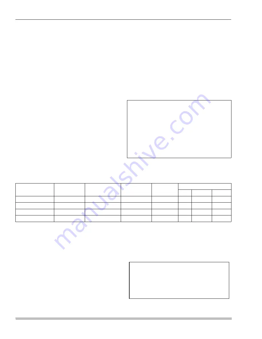
Table 7: 

PSC MOTOR SELECTION

Model Number

Motor Part Num-

ber

Motor Horsepower

Capacitor Part 

Number

Capacitor 

Rating MF

Motor Speed Chart

Cool

Heat LO 

 Heat HI

80 / 64 / 1200 / “A”

024-31969-000

1/3

024-20045-000

7.5

BLK  

BLU  

BLK

100 / 80 / 1600 / “B”

024-27540-000

1/2

024-20046-000

10.0

BLK  

RED 

 BLU

100 / 80 / 2000 / “C”

024-23238-001

1

024-20446-000

15.0

BLK 

RED

 BLU

120 / 96 / 2000 / “C”

024-23238-001

1

024-20446-000

15.0

BLK  

BLU 

BLK

IGNITION CONTROL (P/N 031-01909-000) Normal 

flame sense current is approximately 

2.4 microamps DC (

µ

a)

Low flame signal control lockout point is    

0.15 microamps (DC (

µ

a)

Содержание PxDUA12V06401 series

Страница 1: ...035 17438 001 Rev A 901 EFFICIENCY RATING CERTIFIED CAUTION READ ALL SAFETY GUIDES BEFORE YOU START TO INSTALL YOUR FURNACE SAVE THIS MANUAL TABLE OF CONTENTS GENERAL INFORMATION 2 UNIT INSTALLATION 3...

Страница 2: ...PRODUCT COULD CAUSE PERSONAL INJURY OR PROPERTY DAMAGE IMPROPER INSTALLATION ADJUSTMENT ALTERATION SERVICE OR MAINTENANCE CAN CAUSE INJURY OR PROPERTY DAMAGE REFER TO THIS MANUAL FOR ASSISTANCE OR AD...

Страница 3: ...ptable heat loss calculation for the structure ACCA Manual J or other approved methods may be used The furnace should be located using these guidelines 1 Where a minimum amount of vent piping and elbo...

Страница 4: ...the total input rating of all equipment located in the enclosure b Not less than the sum of the areas of all vent con nectors in the confined space 3 Louvers Grilles and Screens a In calculating free...

Страница 5: ...nds in a general vertical direction and does not con tain offsets exceeding 45 degrees except that a vent system having not more than one 60 degree offset is permitted NOTE This appliance may be commo...

Страница 6: ...nce being operated in operation Adjust thermostat so appli ance will operate continuously 5 Test for draft hood equipped appliance spillage at the draft hood relief opening after 5 minutes of main bur...

Страница 7: ...V UH INPUT MBH H L OUTPUT MBH H L NOM CFM CABINET WIDTH IN AFUE1 LOW FIRE TEMP RISE F HIGH FIRE TEMP RISE MAX OUTLE AIR TEMP F BLOWER TOTAL UNIT AMPS MAX OVER CURRENT PROPECT2 MIN WIRE SIZE AWG 75 FT...

Страница 8: ...removable access panel is recommended in the outlet duct such that smoke or reflected light would be observable inside the casing to indi cate the presence of leaks in the heat exchanger This access...

Страница 9: ...and notes on blower perfor mance tables in this manual Where the return duct system is not complete the return con nection must run full size to a location outside the utility room or basement For fur...

Страница 10: ...s is recommended Refer to Fig ure 6 on page 10 NOTE See crawl space installation for suspending the fur nace in attic installations CRAWL SPACE INSTALLATION The furnace can be hung from floor hoists o...

Страница 11: ...cordance with instructions Specific electrical data is given on the furnace rating plate Provide a power supply separate from all other circuits Install overcurrent protection and disconnect switch pe...

Страница 12: ...OFF position and the main electrical source disconnected complete the low voltage wiring from the ther mostat to the terminal board on the CFM programmable board Connect Class 2 control wiring see Fig...

Страница 13: ...nt 1 Blockage of internal flue gas passage ways 2 Blockage of vent piping 3 Failure of combustion air blower motor Limit Control The high temperature limit control is located on the furnace vestibule...

Страница 14: ...increment find the cubic feet of gas consumed per hour from Table 4 on page 15 NOTE To find the Btuh input multiply the number of cubic feet of gas consumed per hour by the BTU content of the gas in y...

Страница 15: ...cement The temperature rise or temperature difference between the return air and the heated air from the furnace must be within the range shown on the furnace rating plate Application limi tations are...

Страница 16: ...uction for the recommended airflow and Table 6 on page 17 The DELAY Tap should be set in the B position for a two stage condenser This results in a 45 second off delay at 82 of the programmed cooling...

Страница 17: ...002UHC11 L8V1002UHC11 P DUC20V09601 G8V12020UHC11 L8V12020UHC11 COOL TAP ADJ TAP High Low High Low High Low High Low 1340 740 1675 920 2050 1135 2020 1130 A B 1155 635 1555 850 1860 980 1855 960 B B 1...

Страница 18: ...is fixed at 60 seconds for SEER enhance ment HEATING OPERATIONAL SEQUENCE Two Stage Thermostat The ignition control in this furnace is unique to this product The control allows for a 24 volt or a 115...

Страница 19: ...gas valve When power is restored the gas valve will remain deener gized and a restart of the ignition sequence will begin imme diately A momentary loss of gas supply flame blowout or a shorted or open...

Страница 20: ...LOW INDUCER LOW STAGE PRESSURE SWITCH HSI 1ST STAGE MAIN VALVE FLAME SENSE LOW CIRCULATOR HEAT SPEED 1ST STAGE LOW PRESSURE SWITCH CLOSE RECOGNITION HSI WARM UP 17 SEC IGNITION ACTIVATION PERIOD 4 SE...

Страница 21: ...bly for cleaning is as follows 1 Disconnect the power supplied to the furnace 2 Remove the vest and blower panels 3 Disconnect the motor control harness and the power har ness from the motor 4 Remove...

Страница 22: ...including the flue baffle plate rear may be vacuumed or cleaned with hot water if necessary 6 The upper portion of the heat exchanger is now accessi ble With a long flexible wire brush clean inside ea...

Страница 23: ...R REMOVAL FOR CONTROLLER REPLACEMENT Refer to BLOWER CARE on page 21 of this manual for blower removal instructions Rest the blower on its side so the end of the motor is accessible and facing up Wait...

Страница 24: ...ehind a clear view port in the blower compartment door DO NOT remove the furnace blower compartment panel OR turn off furnace power as either action will clear the control s memory of the fault The co...

Страница 25: ...y low gas pressure faulty gas valve faulty hot surface ignitor reversed line polarity or burner problem 8 FLASH This fault is indicated if the flame is lost 5 times during the heating cycle This could...

Страница 26: ...NTROL BOARD P3 S3 2 PIN PLUG SOCKET AT HOT SURFACE IGNITOR P4 S4 3 PIN PLUG SOCKET AT INDUCER MOTOR P5 S5 3 PIN PLUG SOCKET ON VALVE P6 S6 6 PIN PLUG SOCKET ON CFM TIMER BOARD P7 S7 16 PIN PLUG SOCKET...

Страница 27: ...035 17438 001 Rev A 901 Unitary Products Group 27 SERVICE RECORDS...

Страница 28: ...hange without notice Printed in U S A 035 17438 001 Rev A 901 Copyright by York International Corp 2001 All rights reserved Supersedes 035 17438 001 Rev A 801 Unitary 5005 Norman Product York OK Group...

Отзывы: