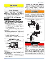
background image

66832-UIM-D-1205

26

Unitary Products Group

The temperature rise, or temperature difference between the return air
and the heated supply air from the furnace, must be within the range
shown on the furnace rating plate and within the application limitations
as shown in Table 8.
After about 15 minutes of operation, determine the furnace temperature
rise. Take readings of both the return air and the heated air in the ducts,
about six feet (1.83 m) from the furnace where they will not be affected
by radiant heat. Increase the blower speed to decrease the temperature
rise; decrease the blower speed to increase the rise.
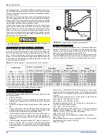
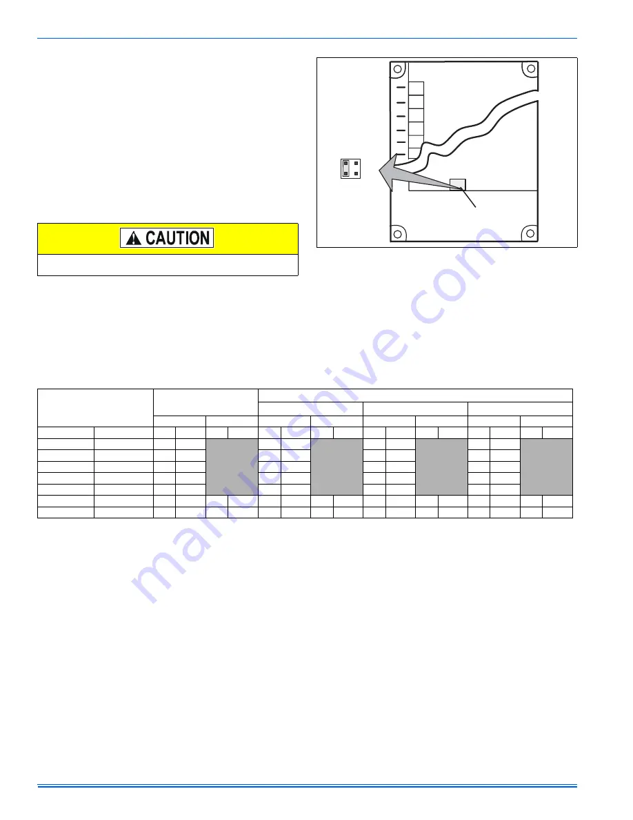
All direct-drive blowers have multi-speed motors. The blower motor
speed taps are located in the control box in the blower compartment.
Refer to Figure 39, and the unit wiring label to change the blower
speed. To use the same speed tap for heating and cooling, the heat ter-
minal and cool terminal must be connected using a jumper wire and
connected to the desired motor lead. Place all unused motor leads on
Park terminals. Two are provided.

ADJUSTMENT OF FAN CONTROL SETTINGS

This furnace is equipped with a time-on/time-off heating fan control. The
fan on delay is fixed at 30 seconds. The fan off delay has 4 settings (60,
90, 120 and 180 seconds). The fan off delay is factory set to 120 sec-
onds. The fan-off setting must be long enough to adequately cool the
furnace, but not so long that cold air is blown into the heated space. The
fan-off timing may be adjusted by positioning the jumper on two of the
four pins as shown in Figure 39.

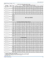
FILTER PERFORMANCE

The airflow capacity data published in Table 17 represents blower per-
formance WITHOUT filters. To determine the approximate blower per-
formance of the system, apply the filter drop value for the filter being
used or select an appropriate value from the Table 16.
The filter pressure drop values in Table 16 are typical values for the
type of filter listed and should only be used as a guideline. Actual pres-
sure drop ratings for each filter type vary between filter manufacturers.

* Hogs Hair Filters are the type supplied with furnace (if supplied).

APPLYING FILTER PRESSURE DROP TO 

DETERMINE SYSTEM AIRFLOW

To determine the approximate airflow of the unit with a filter in place, fol-
low the steps below:

1.

Select the filter type.

2.

Select the number of return air openings or calculate the return
opening size in square inches to determine the proper filter pres-
sure drop.

3.

Determine the External System Static Pressure (ESP) without the
filter.

4.

Select a filter pressure drop from the table based upon the number
of return air openings or return air opening size and add to the
ESP from Step 3 to determine the total system static.

5.

If total system static matches a ESP value in the airflow table (i.e.
0.20 w.c. (50 Pa), 0.60 w.c. (150 Pa), etc.,) the system airflow cor-
responds to the intersection of the ESP column and Model/Blower
Speed row.

6.

If the total system static falls between ESP values in the table (i.e.
0.58 w.c. (144 Pa), 0.75 w.c. (187 Pa), etc.), the static pressure
may be rounded to the nearest value in the table determining the
airflow using Step 5 or calculate the airflow by using the following
example.

Example: For a 75,000 BTUH (21.98 kW) furnace with 2 return open-
ings and operating on high-speed blower, it is found that total system
static is 0.38” w.c. To determine the system airflow, complete the follow-
ing steps:
Obtain the airflow values at 0.30 w.c. (75 Pa) & 0.40 w.c. (99.6 Pa) ESP.

Airflow @ 0.30”: 1408 CFM (39.8 m

3

/min)

Airflow @ 0.40”: 1343 CFM (38.0 m

3

/min)

Subtract the airflow @ 0.30 w.c. (75 Pa) from the airflow @ 0.40 w.c.
(199.6 Pa) to obtain airflow difference.

1343 - 1408 = -65 CFM (1.89 m

3

/min)

Subtract the total system static from 0.30 w.c. (75 Pa) and divide this
difference by the difference in ESP values in the table, 0.40 w.c.
(99.6 Pa) - 0.30 w.c. (75 Pa), to obtain a percentage.
(0.38 - 0.30) / (0.40 - 0.30) = 0.8
Multiply percentage by airflow difference to obtain airflow reduction.
(0.8) X (-65) = -52
Subtract airflow reduction value to airflow @ 0.30 w.c. (75 Pa) to obtain
actual airflow @ 0.38 inwc (94.6 Pa) ESP.
1408 - 52 = 1356

Do not energize more than one motor speed at a time or damage to
the motor will result.

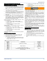
 FIGURE 39:  Typical Heat/Cool Speed Tap Connections

60

90

120

180

PARK

PARK

LINE

XM

COOL

HEAT

FAN OFF
ADJUSTMENT
SWITCHES

TABLE 17: Filter Performance - Pressure Drop Inches W.C. and (kPa)

Airflow Range 

Minimum Opening Size

Filter Type 

Disposable Hogs 

Hair*  Pleated 

1 Opening 

2 Openings 

1 Opening

2 Openings

1 Opening

2 Openings

1 Opening

2 Openings

CFM

Cm/m

In³

In³

inwc

kPa

inwc

kPa

inwc

kPa

inwc

kPa

inwc

kPa

inwc

kPa

0 - 750 

0 - 21.24

230 0.0038

0.01 0.0025

0.01 0.0025

0.15 0.0374

751 - 1000

21.27 - 28.32

330 0.0054

0.05 0.0125

0.05 0.0125

0.2

0.0498

1001 - 1250

28.35 - 35.40

330 0.0054

0.1

0.0249

0.1

0.0249

0.2

0.0498

1251 - 1500

35.42 - 42.47

330 0.0054

0.1

0.0249

0.1

0.0249

0.25 0.0623

1501 - 1750

42.50 - 49.55

380 0.0062

0.15 0.0374

0.14 0.0349

0.3

0.0747

1751 - 2000

49.58 - 56.63

380 0.0062 658 0.0108 0.19 0.0473 0.11 0.0274 0.18 0.0448

0.1

0.0249

0.3

0.0747 0.17 0.0423

2001 & Above 56.66 & Above 463 0.0076 658 0.0108 0.19 0.0473 0.11 0.0274 0.18 0.0448

0.1

0.0249

0.3

0.0747 0.17 0.0423

Содержание G8C

Страница 1: ...orizontal Configuration 5 Vent Blower 5 Top Cap 6 Dimensions 7 Combustible Floor Base Accessory 8 Typical Attic Installation 9 Typical Suspended Furnace Crawl Space Installation 9 Side Return Cutout Markings 10 Horizontal Mount and Filter 10 Downflow Filter 10 Return Filter Grill and Return Duct Installation 11 Gas Valve 11 Upflow Configuration 50 125 MBH Model Only 12 Downflow Configuration 50 12...

Страница 2: ...e within the stated rise range as indicated on the furnace rating plate and the firing input rate must be set to the unit nameplate value e The external static pressure of the air distribution system ductwork must at set for heating operation to be at least 0 10 to 0 20 inches water column based on the input rate of the furnace with the lower value for input rates less than 55 000 btu hr and the u...

Страница 3: ...ized with the air distribution as possible 3 Where adequate combustion air will be available particularly when the appliance is not using outdoor combustion air 4 Where it will not interfere with proper air circulation in the confined space 5 Where the outdoor vent terminal will not be blocked or restricted Refer to VENT CLEARANCES located in SECTION VII of these instructions These minimum clearan...

Страница 4: ...ALLATION POSITION 150 MBH Models This furnace may be installed in an upflow or horizontal position No conversion is necessary This furnace is not approved for downflow application CONVERSION INFORMATION 50 125 MBH Models This furnace may be shipped in either the upflow or the downflow con figuration To convert from upflow to downflow or vice versa it is neces sary only to exchange the top and bott...

Страница 5: ...p cap See Figure 4 15 Install the top cap at the same end of the furnace as the vent blower using the sheet metal screws saved earlier See Figure 1 16 Install the bottom cap on the bottom of the furnace using the sheet metal screws saved earlier See Figure 1 17 The conversion is now complete The furnace may now be installed in the upflow position or in the horizontal position on either side TO CON...

Страница 6: ...ar ducts attached to the plenum and there are two 7 inch round ducts attached to the furnace 1 Take 8 x 14 which equals 112 sq in X 2 which equals 224 square inch then go to round duct size located in Table 2 2 The square inch area for 7 inch round pipe is 38 4 multiply by 2 for two round ducts which equals 76 8 square inch 3 Then take the 224 square inch from the rectangular duct and add it to th...

Страница 7: ...incorrect gas orifice and or a faulty limit switch can cause the furnace to operate above the maximum supply air temperature Refer to sections II III and IX for additional informa tion on correcting the problem FIGURE 5 Dimensions DOWNFLOW UPFLOW A A B E D BOTTOM VIEW F G 29 3 4 29 3 4 C 31 1 2 31 1 2 14 BOTTOM VIEW H J 16 1 4 TABLE 4 Cabinet and Duct Dimensions BTUH kW Input Output Nominal CFM m3...

Страница 8: ...nstructions supplied with the duct con nector for proper installation Refer to the separate accessory parts list at the end of these instructions for the approved accessory duct con nectors When replacing an existing furnace if the existing plenum is not the same size as the new furnace then the existing plenum must be removed and a new plenum installed that is the proper size for the new furnace ...

Страница 9: ...ace then the existing plenum must be removed and a new plenum installed that is the proper size for the new furnace Attach the return plenum to the furnace inlet duct flanges This is typi cally through the use of S cleat material when a metal plenum is used The use of an approved flexible duct connector is recommended on all installations The connection of the plenum to the furnace and all the duc...

Страница 10: ... disposable filters Air velocity must not exceed 650 feet per minute through high velocity cleanable permanent filters Use of a filter that is too small will cause static pressure in the duct system to be too high which will have an adverse effect on heating and cooling operation Downflow Filters Downflow furnaces typically are installed with the filters located above the furnace extending into th...

Страница 11: ...ducts rectangular ducts and or round ducts can be attached to the plenum Route the combustion air and the vent PVC pipes around the access panels for the filters 2 Install the filter s provided or you may install Permanent washable filters Filter should extend through the entire length of the filter rack to prevent air from bypassing the filter IMPORTANT Air velocity through throwaway type filters...

Страница 12: ...le tubing over the pres sure port so that the body of the port is inside the tubing 6 Use a reducer connector to connect the 3 8 0 9 cm ID flexible tube to a 1 4 0 9 cm ID flexible tube that is connected to a U tube manometer or digital pressure measuring equipment IMPORTANT The inlet gas pressure operating range table specifies what the minimum and maximum gas line pressures must be for the furna...

Страница 13: ...ll create an extremely dangerous condition resulting in premature heat exchanger failure excessive sooting high levels of carbon monoxide personal injury property damage a fire hazard and or death High altitude and propane LP conversions are required in order for the appliance to satisfactory meet the application An authorized distributor or dealer must make all gas conversions In Canada a certifi...

Страница 14: ... type cycle rate adjustments Follow the thermostat manufacturer s instructions IMPORTANT Set the heat anticipator in the room thermostat to 0 40 amps Setting it lower will cause short cycles Setting it higher will cause the room temperature to exceed the set points The 24 volt 40 VA transformer is sized for the furnace components only and should not be connected to power auxiliary devices such as ...

Страница 15: ...long this wire This communication makes the second furnace blower come on at the same time and on the same speed as the first furnace blower Single Wire Twinning Instructions Connect the control wiring as shown in the Figure 23 1 Connect the low voltage wiring from the wall thermostat to the ter minal strip on the control board of Furnace 1 2 Connect a wire from the TWIN terminal of Furnace 1 to t...

Страница 16: ...ll for first stage heat W1 signal from the wall thermo stat Furnace 1 will start the ignition sequence and the burners will light About thirty seconds after the burners light the blowers on both furnaces will come on in heating speed When the thermostat is satis fied the burners will shut off and after the selected blower off delay time both blowers will shut off at the same time On a call for sec...

Страница 17: ...ized standard or a masonry or concrete chimney lined with a material acceptable to the authority having jurisdiction Venting into an unlined masonry chimney or concrete chimney is prohibited Whenever possible B 1 metal pipe should be used for venting Where use of an existing chimney is unavoidable the following rules must be followed 1 The masonry chimney must be built and installed in accordance ...

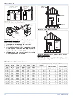
Страница 18: ...PE FLUE PIPE BURNER ACCESS PANEL CELLAR WALL OPTIONAL SIDEWALL VENT SYSTEM field supplied TOP COVER VENT DAMPER FIGURE 31 Typical Chimney Connections FIGURE 32 Horizontal Air Inlet Outlet and Chimney Connections FURNACE WATER HEATER CHIMNEY OR GAS VENT OPENING OPENING FURNACE WATER HEATER OUTLET AIR DUCT INLET AIR DUCT TABLE 10 Horizontal Sidewall Venting Clearances Horizontal Vent Length Ft m wit...

Страница 19: ...t will not be affected by wind gusts light snow airborne leaves or allow recirculation of flue gases 4 Termination should be located where it will not be damaged or exposed to flying stones balls etc 5 Termination should be positioned where vent vapors are not objec tionable 6 Horizontal portions of the vent system must slope upwards and be supported to prevent sagging The vent system may be suppo...

Страница 20: ... manually adjustable louvers are not permitted for use 4 A automatically operated damper or automatically adjustable lou vers shall be interlocked so that the main burner cannot operate unless either the damper or the louver is in the fully open position FIGURE 34 Combustion Airflow Path Through The Furnace Casing to the Burner Box This type of installation requires that the supply air to the appl...

Страница 21: ...pliance unless otherwise permitted by the authority having jurisdiction The opening shall be located within 12 30 5 cm horizontally from the burner level of the appliance Refer to AIR SOURCE FROM OUTDOORS AND VENT AND SUPPLY AIR SAFETY CHECK in these instructions for additional information and safety check procedure 2 The duct shall be either metal or a material meeting the class 1 requirements of...

Страница 22: ...nted gas CARBON MONOXIDE POISONING HAZARD Failure to follow the steps outlined below for each appliance connected to the venting system being placed into operation could result in carbon monoxide poisoning or death The following steps shall be followed for each appliance connected to the venting system being placed into operation while all other appliances connected to the venting system are not i...

Страница 23: ...odule will energize open the main gas valve c After flame is established the supply air blower will start in about 30 seconds IMPORTANT Burner ignition may not be satisfactory on first startup due to residual air in the gas line or until gas manifold pressure is adjusted The ignition control will make 3 attempts to light before lock ing out With furnace in operation check all of the pipe joints ga...

Страница 24: ...re and temperature correction factor of 0 960 times 3600 then divided by the time it took to measure 0 0566 m3 of gas from the gas meter For Propane LP Gas multiply the Heat content of the gas MJ m3 or Default 93 14 times 0 00283 m3 of gas measured at the gas meter times a barometric pressure and temperature correction factor of 0 960 times 3600 then divided by the time it took to measure 0 0283 c...

Страница 25: ... wrench 10 Turn the electrical and gas supplies back on and with the burners in operation check for gas leakage around the gas valve pressure port for leakage using an approved gas detector a non corrosive leak detection fluid or other leak detection methods ADJUSTMENT OF TEMPERATURE RISE Be sure to relight any gas appliances that were turned off at the start of this input check TABLE 15 Inlet Gas...

Страница 26: ...al System Static Pressure ESP without the filter 4 Select a filter pressure drop from the table based upon the number of return air openings or return air opening size and add to the ESP from Step 3 to determine the total system static 5 If total system static matches a ESP value in the airflow table i e 0 20 w c 50 Pa 0 60 w c 150 Pa etc the system airflow cor responds to the intersection of the ...

Страница 27: ...ow 1820 51 5 1757 49 8 1664 47 1 1594 45 1 1506 42 6 1405 39 8 1287 36 4 1137 32 2 125 100 36 6 29 3 2 D High 2483 70 3 2392 67 7 2282 64 6 2161 61 2 2032 57 5 1887 53 4 1739 49 2 1567 44 4 Med High 2198 62 2 2123 60 1 2039 57 7 1930 54 7 1830 51 8 1708 48 4 1550 43 9 1413 40 0 Med Low 1999 56 6 1916 54 3 1859 52 6 1778 50 3 1684 47 7 1576 44 6 1451 41 1 1315 37 2 Low 1832 51 9 1775 50 3 1709 48 4...

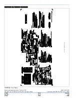
Страница 28: ...32 UIM D 1205 Copyright by York International Corp 2005 All rights reserved Supersedes 66832 035 19991 001 Rev C 0805 Unitary 5005 Norman Product York OK Group Drive 73069 SECTION XI WIRING DIAGRAM FIGURE 40 Wiring Diagram Nov 18 2005 03 43PM a5kps v1 50 ...

Отзывы: