background image

11

Unitary Products Group

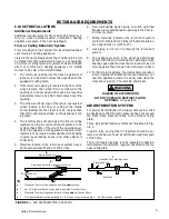
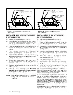
FIGURE 9 --

DUCT CONNECTOR SCREW

ATTACHMENT

SUPPLY DUCT

LOCATOR BRACKET

NAILS, FLAT HEAD SCREWS

OR STAPLES

SCREWS

FLOOR

FIGURE 10 --

DUCT CONNECTOR TAB

ATTACHMENT

SUPPLY DUCT

LOCATOR BRACKET

NAILS, FLAT HEAD SCREWS

OR STAPLES

FLOOR

BEND TABS UNDER

DUCT OPENING TO

SECURE TO THE

SUPPLY DUCT.

INSTALLATION OF SCREW ATTACHMENT

DUCT CONNECTOR

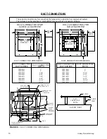
1. Make floor cut out as shown in Figure 8.

2. Determine the depth of the floor cavity from the sur-

face of the floor to the top of the supply air duct and

select the appropriate duct connector from the chart.

3. Place locating bracket (supplied with the duct con-

nector) to the back edge of the floor opening. See

Figure 9.

4. Apply a water based duct sealant to the 1/2” supply

duct attachment flange of the duct connector.

5. Determine which of the four positions the duct con-

nector best centers over the supply duct and insert

it through the floor cutout.

6. When properly aligned with the supply duct, secure

the duct connector to the floor with nails, flat head

screws or staples.

7. Use screws as required to secure the duct connector

to the supply duct.

8. Cut out the opening to the supply duct.

If sealant

was not used, the installer should tape the mat-

ing flanges to provide a good air seal.

NOTE:

Duct sealant and tape must be U.L. classified as

meeting HUD standard 3280.715 and U.L.

standard 181.

INSTALLATION OF TAB ATTACHMENT

DUCT CONNECTORS

1. Make floor cut out as shown in figure 8.

2. Determine the depth of the floor cavity from the sur-

face of the floor to the top of the supply air duct and

select the appropriate duct connector from the chart.

3. Place locating bracket (supplied with the duct con-

nector) to the rear of the floor area for the furnace.

See Figure 10.

4. Determine which of the four positions the duct con-

nector best centers over the supply duct and insert

it through the floor cutout.

5. Mark cut--out location on the supply duct and re-

move the duct connector.

6. Cut out the opening to the supply duct.
7. Bend tabs down through and back up under the sup-

ply duct.

8. Secure the duct connector to the floor with nails, flat

head screws or staples.

The duct connector is designed for use on ducts down to

12” in width. When using the connector on smaller width

ducts, there will not be sufficient clearance to bend the

tabs on two sides of the duct connector.
In such cases the tabs may be attached to the sides of

the duct by using sheet metal screws or other suitable

fasteners. Holes for sheet metal screws are provided in

three (3) tabs on each side of the duct connector. If more

than 3 tabs need to be used to provide a more secure and

air tight connection, the remaining tabs can also be fas-

tened to the duct with screws after drilling the required

screw holes.
If tape is used to provide a better air seal, it should be a

type approved by the applicable national or local codes.

Содержание DLAS

Страница 1: ...ation adjustment service or maintenance can cause injury or property dam age Please refer to all the instructions of this manual for proper installation procedures Im proper installation will void the...

Страница 2: ...nace Doors 19 Finish and Trim 19 Furnace and Air Conditioner Installations 19 HIGH ALTITUDE DERATION CHART 20 Natural Gas 20 Propane Gas 20 REPAIR PARTS 21 22 LIST OF FIGURES FIGURE 1 Furnace Dimensio...

Страница 3: ...0BDF NATURAL GAS 70 000 57 000 DGAT075BDF NATURAL GAS 75 000 61 000 DGAT090BDF NATURAL GAS 90 000 72 000 DLAS Automatic Ignition Heating Only No Coil Cabinet Model No Factory Equipped for use with Inp...

Страница 4: ...nt CSA stan dard CAN CGA Z240 4 2 Installation Require ments for Propane Appliances and Equipment in Recreational Vehicles 2 Unit electrical wiring and grounding shall complywith current CSA standard...

Страница 5: ...cation of 200 or less 6 Non combustible pans having one inch upturned flanges are located beneath openings in the floor re turn duct system 7 Wiring materials located in the return duct system conform...

Страница 6: ...er grill an undercut of 2 1 2 will provide 50 Sq In of free area 1 The closet door MUST have a minimum of 250 Square In ches of free area in the upper half of the door and a mini mum of 50 Square Inch...

Страница 7: ...installed on a new home do the following 1 Inspect the furnace top collars for signs of insulation or ceiling debris which might have fallen in during cutting of the ceiling and roof holes Remove all...

Страница 8: ...ITCH SLANT FLASHING 3 12 PITCH DLAS COAS Furnaces DGAT DGAM COAT CGAT Furnace Installation Dimensions Installation Dimensions A Adjustable Height B Adjustable Height 4000 7101 C 4000 7121 C 4000 7141...

Страница 9: ...DGAT DGAM COAT CGAT Furnace Installation Dimensions Installation Dimensions A Adjustable Height B Adjustable Height 4000 8101 C 4000 8181 C 4000 9161 A 4000 9181 A 85 to 101 99 to 129 101 to 117 115 t...

Страница 10: ...he furnace may be installed on combustible flooring without a separate sub base DUCT CONNECTOR DIMENSIONS DUCT CONNECTOR DIMENSIONS DUCT CONNECTORS FOR SCREW ATTACHMENT DUCT CONNECTORS FOR TAB ATTACHM...

Страница 11: ...0 715 and U L standard 181 INSTALLATION OF TAB ATTACHMENT DUCT CONNECTORS 1 Make floor cut out as shown in figure 8 2 Determine the depth of the floor cavity from the sur face of the floor to the top...

Страница 12: ...w hole is provided in the pipe and collar Excessively long screws may extend to flue pipe and puncture it Screws are not to exceed 1 1 2 in length NOTE Combustion air tube and flue pipe are part of th...

Страница 13: ...n the left side of the furnace See Figure 14 If conduit is used it should be secured to the control box 3 Connect the hot wire to the BLACK pigtail lead and the neutral wire to the WHITE pigtail lead...

Страница 14: ...bove the floor The preferred location is on an inside wall situated in an area with good air circulation and where the temperature will be reasonably representative of other living areas the thermosta...

Страница 15: ...itch To Earth Ground Neutral L1 115 VAC To A C Condensing Unit If equipped Incoming Power Must Be Polarized Observe Color Coding NEUTRALS Ground Screw HEAT COOL L1 XFMR COM 24 VAC RED BLK BRN WHT WHT...

Страница 16: ...Earth Ground Neutral L1 115 VAC To A C Condensing Unit If equipped Incoming Power Must Be Polarized Observe Color Coding NEUTRALS Ground Screw HEAT COOL L1 XFMR COM 24 VAC RED BLK WHT WHT BLK BLU RED...

Страница 17: ...r is then reduced to 10 W C IMPORTANT When converting valve from or to Pro pane gas it will be necessary to change main burner ori fice to prevent an underfired or overfired condition See label inside...

Страница 18: ...PRONOUNCED YELLOW WITH ORANGE TIPS LIGHT BLUE NO BLUE TIPS EXTENDING FROM THE END OF THE BURNER DARK BLUE DARK BLUE LONG AND EXTREMELY PRONOUNCED BLUE TIPS EXTENDING FROM THE END OF THE BURNER WHTISH...

Страница 19: ...e and air condi tioner form operating at the same time This interlock system usually contains a heat cool switch which must be turned to either HEAT or COOL to activate either heating or cooling opera...

Страница 20: ...0 128 30 9951 1281 0 136 29 9951 1361 0 152 24 9951 1521 PROPANE GAS 56 000 Input 70 000 Input 75 000 Input 90 000 Input Elevation Orifice Dia Drill Size Part Orifice Dia Drill Size Part Orifice Dia D...

Страница 21: ...flow Furnace Repair Parts List for DGAM056BDF DLAS056BDF DGAM075BDF DLAS075BDF Repair Parts List for DGAT056BDF DGAT070BDF DGAT075BDF DGAT090BDF 13 26 27 28 15 14 14 30 34 35 33 32 31 29 22 21 16 23 2...

Страница 22: ...EN 145 CLOSE 115 Limit Switch OPEN 150_ CLOSE 120_ 21 All 7970 5851 A Burner Assembly Less Gas Valve 22 All 1474 0521 Hot Surface Ignitor 23 All 7970 179 Ignitor Shield 24 All 7945 1631 A Mounting Pla...

Страница 23: ...23 Unitary Products Group...

Страница 24: ...ary Products Group Subject to change without notice Printed in U S A Copyright E by Unitary Products Group 1999 All rights reserved 1973 106 F Rev 2 599 5005 York Drive Unitary Products Group Norman O...

Отзывы: