16
Unitary Products Group
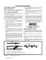
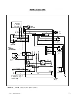
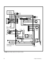
FIGURE 18
-- WIRING DIAGRAM FOR DGAM SERIES
Blend Air
Control Box
(If equipped)
G
RH
Y
Upper
Limit
Switch
Lower
Limit
Switch
Combustion
Blower
Motor
Hot Surface
Ignitor
Gas
Valve
Blower
Motor
System
Switch
To Earth Ground
Neutral
L1
115
VAC
To A/C
Condensing
Unit (If
equipped)
Incoming Power Must
Be Polarized. Observe
Color Coding
NE
UT
RA
LS
Ground
Screw
HE
A
T
COOL
L1
XFM
R
COM
24
VAC
RED
BLK
WHT
WHT
BLK
BLU
RED
LO
A
D
LI
N
E
WHT
WHT
BLK
S
ens
or
R
od
BLK
BRN
BRN
BLU
BLU
GRN
ORG
BLU
GRY
W
G
R
Y
C
BL
K
BL
K
BL
K
GRN
WH
T
RE
D
YEL
BLK
GRN
WHT
Transformer
YEL
RED
WH
T
WHT
BLK
RED
W
Combustion Air
Switch
1
3
5 6 7 8 9
2
4
1
2
1
2
3
4
5
6
7
8
9
2
1
3
4
5
6
Содержание DLAS
Страница 23: ...23 Unitary Products Group...

