Unitary products group AHV8 UH Скачать руководство пользователя страница 5

271001-UIM-A-0407

Unitary Products Group

5

1.

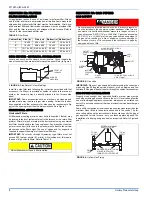
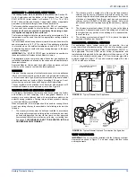
The Air Temperature Rise is determined by subtracting the Return
Air Temperature Reading from the Supply Air Temperature Read-
ing.

2.

The External Static Pressure is determined by adding the Supply
Duct Static Pressure reading to the Return Duct Static Pressure
reading and adding the pressure drop across any applied a-coil
and return air filter.

Tables 2 and 3 are to be used as a guide only to help the installer deter-
mine if the duct sizes are large enough to obtain the proper air flow
(CFM) through the furnace. Tables 2 and 3 ARE NOT to be used to
design ductwork for the building where the furnace is being installed.
There are several variables associated with proper duct sizing that are
not included in the tables. To properly design the ductwork for the build-
ing, refer to the ASHRAE Fundamentals Handbook, Chapter on “DUCT
DESIGN” or a company that specializes in Residential and Modular
Home duct designs.

IMPORTANT: 

The minimum plenum height is 12” (30.5 cm). The fur-

nace will not operate properly on a shorter plenum height. The mini-
mum recommended rectangular duct height is 4 inches (10 cm)
attached to the plenum.

IMPORTANT: 

The air temperature rise should be taken only after the

furnace has been operating for at least 15 minutes. Temperatures and
external static pressures should be taken 6” (15 cm) past the first bend
from the furnace in the supply duct and the return duct. If an external fil-
ter box or an electronic air cleaner is installed, take the return air read-
ings before the filter box or air cleaner.

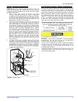
If a matching cooling coil is used, it may be placed directly on the fur-
nace outlet and sealed to prevent leakage. Follow the coil instructions
for installing the supply plenum. On all installations without a coil, a
removable access panel is recommended in the outlet duct such that
smoke or reflected light would be observable inside the casing to indi-
cate the presence of leaks in the heat exchanger. This access cover
shall be attached in such a manner as to prevent leaks.
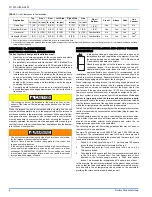
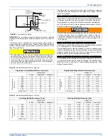
TABLE 2: 

Minimum Duct Sizing For Proper Airflow

Airflow

Return

1

Rectangular

2

Round

2

Supply

3

Rectangular

2

Round

2

CFM (m³)

In² (cm²)

in. x in. (cm x cm)

in. (cm) dia.

In² (cm²)

in. x in. (cm x cm)

in. (cm) dia.

1,200 (34)

280 (1806)

14 x 20 (35.6 x 50.8)

18 (45.7)

216 (1393)

12 x 18 (30.5 x 45.7)

16 (40.6)

1,600 (45.3)

360 (2322)

18 x 20 (45.7 x 50.8)

22 (55.8)

280 (1806)

14 x 20 (35.6 x 50.8)

18 (45.7)

2,000 (56.6)

440 (2838)

20 x 22 (50.8 x 55.8)

24 (60.9)

390 (2516)

16 x 22 (40.6 x 55.8)

22 (55.8)

NOTE: This chart does not replace proper duct sizing calculations or take into account static pressure drop for run length and fittings. Watch out for the temperature rise and static pressures.

1. Maximum return air velocity in rigid duct @ 700 feet per minute (213 m/min).
2. Example return main trunk duct minimum dimensions.
3. Maximum supply air velocity in rigid duct @ 900 feet per minute (274m/min).

TABLE 3: 

Round Duct Size

Round Duct Size

Calculated Area For Each Round Duct Size

inches (cm)

Sq.in (cm

2

)

5 (13)

19.6 (126)

6 (15)

28.2 (182)

7 (18)

38.4 (248)

8 (20)

50.2 (324)

9 (23)

63.6 (410)

10 (25)

78.5 (506)

11 (28)

95 (613)

12 (30)

113.1 (730)

13 (33)

132.7 (856)

14 (36)

153.9 (993)

The supply air temperature MUST NEVER  exceed the Maximum
Outlet Air Temperature
, specified on the nameplate.
Operating the furnace above the maximum outlet air temperature
will cause the heat exchanger to overheat, causing premature heat
exchanger failure. Improper duct sizing, dirty air filters, incorrect
manifold pressure, incorrect gas orifice and/or a faulty limit switch
can cause the furnace to operate above the maximum supply air
temperature. Refer to sections II, III and VIII for additional informa-
tion on correcting the problem.

Содержание AHV8 UH

Страница 1: ...ited to building electrical and mechanical codes LIST OF SECTIONS SAFETY 1 DUCTWORK 4 FILTERS 8 GAS PIPING 8 ELECTRICAL POWER 10 VENT SYSTEM 14 SAFETY CONTROLS 19 START UP AND ADJUSTMENTS 20 WIRING DI...

Страница 2: ...s from combustible materials as listed under Clearances to Combustibles in Table 1 Provide clearances for servicing ensuring that service access is allowed for both the burners and blower These models...

Страница 3: ...ed Never store items such as the following on near or in contact with the fur nace 1 Spray or aerosol cans rags brooms dust mops vacuum cleaners or other cleaning tools 2 Soap powders bleaches waxes o...

Страница 4: ...erates at the specified external static pressure and within the air temperature rise specified on the nameplate Table 2 is a guide for determining whether the rectangular duct system that the furnace...

Страница 5: ...supply plenum On all installations without a coil a removable access panel is recommended in the outlet duct such that smoke or reflected light would be observable inside the casing to indi cate the...

Страница 6: ...floor support with required service accessibility IMPORTANT If an external mounted filter rack is being used see the instructions provided with that accessory for proper hole cut size HORIZONTAL MODEL...

Страница 7: ...removed and a new plenum installed that is the proper size for the new furnace Attach the return plenum to the furnace inlet duct flanges This is typi cally through the use of S cleat material when a...

Страница 8: ...IV GAS PIPING GAS SAFETY IMPORTANT Plan your gas supply before determining the correct gas pipe entry Use 90 degree service elbow s or short nipples and con ventional 90 degree elbow s to enter throu...

Страница 9: ...ing The gas valve body is a very thin casting that cannot take any external pressure Never apply a pipe wrench to the body of the gas valve when installing piping A wrench must be placed on the octag...

Страница 10: ...er must take every precaution to insure that the furnace has been converted to the proper gas orifice size when the furnace is installed Do not attempt to drill out any orifices to obtain the proper o...

Страница 11: ...ty is corrected Refer to FURNACE DIAGNOSTICS section of the User s Information Maintenance Service Manual provided with this furnace for symptoms of reversed power supply polarity LOW VOLTAGE CONTROL...

Страница 12: ...Stage Cool Y2 Second Stage Cool W2 Second Stage Heat G Fan R 24 Volt Hot W First Stage Heat Y1 First Stage Cool R 24 Volt Hot Y Y2 Single Second Stage Cool Y2 Second Stage Cool W2 Second Stage Heat G...

Страница 13: ...versing Valve Energized in Cool O Reversing Valve Energized in Cool O Reversing Valve Energized in Cool Y2 Second Stage Heat Cool DHM Dehumidistat HUM Dehumidification Open on Humidity Rise Y2 Second...

Страница 14: ...ssory Connections FIGURE 12 Vent Termination 115 VOLT HUMIDIFER 115 VOLT ELECTRONIC AIR CLEANER EAC HOT HUM HOT BLK WHT EAC HUM NEUTRALS SWITCHED CIRCUITS BLK WHT LOWEST DISCHARGE OPENING LISTED CAP L...

Страница 15: ...the authority having jurisdiction Venting into an unlined masonry chimney or concrete chimney is prohibited Whenever possible B 1 metal pipe should be used for venting Where use of an existing chimne...

Страница 16: ...nd from any direction will not create a positive pressure in the vicinity of the vent FIGURE 17 Home Layout L E D B V V V X V B V J X B B B V V F V C B X V I V G H A M K OPERABLE FIXED CLOSED VENT TER...

Страница 17: ...obtain proper air for combus tion and ventilation in confined spaces Combustion Air Source From Outdoors The blocking effects of louvers grilles and screens must be given con sideration in calculatin...

Страница 18: ...el of the appliance Refer to COMBUSTION AIR SOURCE FROM OUTDOORS and VENT AND SUPPLY AIR SAFETY CHECK in these instructions for additional information and safety check procedure 2 The duct shall be ei...

Страница 19: ...ustion air blower heat exchanger or a blocked vent pipe connection Corrective action is required These are manual reset controls that must be reset before operation can continue PRESSURE SWITCHES This...

Страница 20: ...in w c 0 3 73 kPa in order to measure the gas line and the manifold pressures 4 You will need a 3 32 Allen wrench for the pressure port plugs in the gas valve 5 You will need 2 pieces of 1 8 0 3 cm ID...

Страница 21: ...at the gas meter times a barometric pressure and temperature correction factor of 0 960 times 3600 then divided by the time it took to measure 0 10 m3 of gas from the gas meter For Propane LP Gas mul...

Страница 22: ...h low and high have been calibrated at the factory Additional pressure adjustment should not be necessary If adjustment is necessary set to the following specifications After adjustment check for gas...

Страница 23: ...eed to the other Tap B is the humid profile This profile is best suited for installations where the humidity is frequently very high during cooling season such as in the southern part of the country O...

Страница 24: ...pressure switch or miswiring 3 RED FLASHES This indicates the normally open pressure switch contact did not close after the inducer was energized This could be caused by a number of problems faulty i...

Страница 25: ...ry the LED will flash two green flashes To clear the memory push the LAST ERROR button and hold it for more than five seconds The LED will flash three green flashes when the memory has been cleared th...

Страница 26: ...47 5 30 9 47 5 30 9 1540 1001 1540 1001 C B 43 6 28 3 43 6 28 3 1440 936 1440 936 B C 40 8 26 5 40 8 26 5 1320 858 1320 858 D B 37 4 24 3 37 4 24 3 1400 910 1400 910 C A 39 6 25 8 39 6 25 8 1200 780 1...

Страница 27: ...stem static from 0 60 w c 150 Pa and divide this by 0 1 w c 25 Pa 0 68 170 Pa 0 60 150 Pa 0 08 20 Pa 0 08 20 Pa 0 1 25 Pa 0 8 Multiply this by 2 to obtain the percentage reduction in airflow 0 8 x 0 0...

Страница 28: ...Printed in U S A 271001 UIM A 0407 Copyright by York International Corp 2007 All rights reserved Supersedes 167187 UIM C 0806 Unitary 5005 Norman Product York OK Group Drive 73069 SECTION IX WIRING D...

Отзывы: