


271001-UIM-A-0407
Unitary Products Group
27
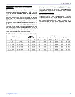
APPLYING FILTER PRESSURE DROP TO
DETERMINE SYSTEM AIRFLOW
To determine the approximate airflow of the unit with a filter in place, fol-
low the steps below:
1.
Select the filter type.
2.
Select the number of return air openings or calculate the return
opening size in square inches to determine the proper filter pres-
sure drop.
3.
Determine the External System Static Pressure (ESP) without the
filter.
4.
Select a filter pressure drop from the table based upon the number
of return air openings or return air opening size and add to the
ESP from Step 3 to determine the total system static.
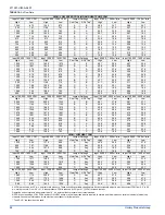
5.
If total system static is less than 0.6” w.c. (150 Pa), then the CFM
is the value in Table 15.
6.
If the total system static is greater than 0.6” w.c. (150 Pa), then the
CFM is reduced by 2% per 0.1” w.c. (25 Pa) increase in static and
can be calculated by using the following example:
Example: For an 80,000 BTUH (23.4 kW) furnace operating on HI
COOL TAP B and ADJUST TAP A, it is found that total system static is
0.68” w.c. (170 Pa).
To determine the system airflow, complete the following steps:
Airflow @ 0.60”: 1400 CFM (39.6 m
3
/min)
Subtract the total system static from 0.60” w.c. (150 Pa) and divide this
by 0.1” w.c. (25 Pa).
0.68 (170 Pa) - 0.60 (150 (Pa) = 0.08 (20 Pa)
0.08 (20 Pa) / 0.1 (25 Pa) = 0.8
Multiply this by 2% to obtain the percentage reduction in airflow.
0.8 x 0.02 = 0.016
Multiply percentage reduction in airflow by the airflow in the table to
obtain the airflow reduction.
0.016 x 1400 (39.6 m
3
/min) = 22 (0.6 m
3
/min)
Subtract airflow reduction value from airflow in the table to obtain actual
airflow @ 0.68” w.c. (170 Pa) ESP.
1400 (39.6 m
3
/min) - 22 (0.6 m
3
/min) = 1378 (39.0 m
3
/min).
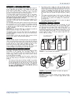
TABLE 17:
Field Installed Accessories - Non Electrical
MODEL NO.
DESCRIPTION
USED WITH
1NP0347
PROPANE (LP) CONVERSION KIT
ALL MODELS
1PS0313
HIGH ALTITUDE PRESSURE SWITCH KIT
(DOES NOT INCLUDE ORIFICES)
57, 80, 100
MBH
1PS0314
120
MBH
1SR0302
SIDE RETURN FILTER KIT 1” FILTER
ALL MODELS
1SR0200
SIDE RETURN FILTER KIT 1-4” FILTER
ALL MODELS
1BR0114
BOTTOM RETURN FILTER KIT 1” FILTER
14-1/2” CABINETS
1BR0214
BOTTOM RETURN FILTER KIT 1-4” FILTER
14-1/2” CABINETS
1BR0117
BOTTOM RETURN FILTER KIT 1” FILTER
17-1/2” CABINETS
1BR0217
BOTTOM RETURN FILTER KIT 1-4” FILTER
17-1/2” CABINETS
1BR0121
BOTTOM RETURN FILTER KIT 1” FILTER
21” CABINETS
1BR0221
BOTTOM RETURN FILTER KIT 1-4” FILTER
21” CABINETS
1BR0124
BOTTOM RETURN FILTER KIT 1” FILTER
24-1/2” CABINETS
1BR0224
BOTTOM RETURN FILTER KIT 1-4” FILTER
24-1/2” CABINETS
1HF0801
INTERNAL FILTER KIT WITH 1” FIBER FILTER
ALL MODELS


