


271001-UIM-A-0407
4
Unitary Products Group
SECTION II: DUCTWORK
DUCTWORK GENERAL INFORMATION
The duct system’s design and installation must:
1.
Handle an air volume appropriate for the served space and within
the operating parameters of the furnace specifications.
2.
Be installed in accordance with standards of NFPA (National Fire
Protection Association) as outlined in NFPA pamphlets 90A and
90B (latest editions) or applicable national, provincial, or state, and
local fire and safety codes.
3.
Create a closed duct system. For residential and Modular Home
installations, when a furnace is installed so that the supply ducts
carry air circulated by the furnace to areas outside the space con-
taining the furnace, the return air shall also be handled by a duct(s)
sealed to the furnace casing and terminating outside the space
containing the furnace.
4.
Complete a path for heated or cooled air to circulate through the
air conditioning and heating equipment and to and from the condi-
tioned space.
When the furnace is used in conjunction with a cooling coil, the coil
must be installed parallel with, or in the supply air side of the furnace to
avoid condensation in the primary heat exchanger. When a parallel flow
arrangement is used, dampers or other means used to control airflow
must be adequate to prevent chilled air from entering the furnace. If
manually operated, the damper must be equipped with means to pre-
vent the furnace or the air conditioner from operating unless the damper
is in full heat or cool position.
DUCTWORK INSTALLATION AND SUPPLY PLENUM
CONNECTION
A proper heat loss/gain calculation should be done on all
installations for proper application of equipment. From this,
the ductwork sizing can be calculated. ACCA Manual J and
D and industry standards are helpful.
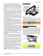
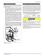
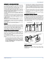
Attach the supply plenum to the furnace or coil outlet duct
connection flanges. This is typically through the use of S
cleat material when a metal plenum is used. The use of an
approved flexible duct connector is recommended on all
installations to prevent noise transmission. All connections should be
sealed to prevent air leakage. Sheet metal should be crosshatched to
eliminate any popping when the indoor fan is energized.
When replacing an existing furnace, if the existing supply plenum is not
the same size as the new furnace then the existing plenum must be
removed and a new plenum installed that is of the proper size for the
new furnace. If the plenum is shorter than 12” (30.5 cm) the turbulent air
flow may cause the limit controls not to operate as designed, if at all.
The duct system is a very important part of the installation.
If the duct
system is improperly sized the furnace will not operate properly.
The ducts attached to the furnace plenum should be of sufficient size so
that the furnace operates at the specified external static pressure and
within the air temperature rise specified on the nameplate.
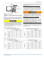
Table 2 is a guide for determining whether the rectangular duct system
that the furnace is being connected to be of sufficient size for proper fur-
nace operation.
Use the Example below to help you in calculating the duct area to deter-
mine whether the ducts have sufficient area so that the furnace oper-
ates at the specified external static pressure and within the air
temperature rise specified on the nameplate.
The following are general duct sizing guidelines that may not serve to
requirements of every application.
Example: The furnace input is 80,000 BTUH with 1,200 CFM blower
requirement. The recommended duct area is 216 sq.in, there are two 8
x 12 rectangular ducts attached to the plenum and there are two 7 inch
round ducts attached to the furnace.
1.
Take 8 x 12, which equals 96 sq.in. X 2, which equals 192 square
inches then go to round duct size located in Table 3.
2.
The square inch area for 7 inch round ducts is 38.4 sq. in. x 2 =
76.8 square inches.
3.
Then take the 192 square inch from the rectangular duct and add it
to the 76.8 sq.in. of round duct. The total square inch of duct
attached to the furnace supply plenum is 268.8 total square
inches. This exceeds the recommended 216 square inch of duct.
In this example, the duct system attached to the plenum has a sufficient
area so that the furnace operates at the specified external static pres-
sure and within the air temperature rise specified on the nameplate,
providing the return duct is properly sized as well.
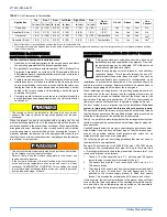
TABLE 1:
Unit Clearances to Combustibles
Application
Top
Front
Rear
Left Side
Right Side
Flue
Floor/
Bottom
Closet
Alcove
Attic
Line
Contact
In. (cm) In. (cm) In. (cm)
In. (cm)
In. (cm)
In. (cm)
Downflow
1 (2.5
6 (15.2)
0 (0.0)
0 (0.0)
3 (7.6)
6 (15.2)
1 (2.5)
1
Yes
Yes
Yes
No
Downflow B-Vent
1 (2.5)
3 (7.6)
0 (0.0)
0 (0.0)
0 (0.0)
1 (2.5)
1 (2.5)
1
Yes
Yes
Yes
No
Horizontal
1 (2.5)
6 (15.2)
0 (0.0)
0 (0.0)
3 (7.6)
6 (15.2)
Combustible
No
Yes
Yes
Yes
2
Horizontal B-Vent
1 (2.5)
3 (7.6)
0 (0.0)
0 (0.0)
0 (0.0)
1 (2.5)
Combustible
No
Yes
Yes
Yes
2
1. Special floor base or air conditioning coil required for use on combustible floor.
2. Line contact only permitted between lines formed by the intersection of the rear panel and side panel (top in horizontal position) of the furnace jacket and building
joists, studs or framing.
The cooling coil must be installed in the supply air duct, down-
stream of the furnace. Cooled air may not be passed over the heat
exchanger.
The duct system must be properly sized to obtain the correct airflow
for the furnace size that is being installed.
Refer to Table 8 and the furnace rating plate for the correct rise
range and static pressures
If the ducts are undersized, the result will be high duct static pres-
sures and/or high temperature rises which can result in a heat
exchanger OVERHEATING CONDITION. This condition can result
in premature heat exchanger failure, which can result in personal
injury, property damage, or death.


