Unitary products group AHV8 UH Скачать руководство пользователя страница 26

271001-UIM-A-0407

26

Unitary Products Group
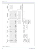
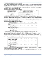
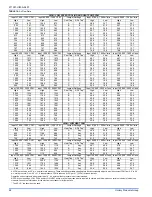
TABLE 16: 

Air Flow Data

HIGH / LOW SPEED COOLING AND HEAT PUMP CFM

Input 57,000 - 1200 CFM

Input 80,000 - 1200 CFM

Jumper Settings

Input 57,000 - 1200 m³/min

Input 80,000 - 1200 m³/min

High

Low

High

Low

Cool Tap

ADJ Tap*

High

Low

High

Low

1342

872

1342

872

A

B

38.0

24.7

38.0

24.7

1155

751

1155

751

B

B

32.7

21.3

32.7

21.3

1220

793

1220

793

A

A

34.5

22.5

34.5

22.5

1050

683

1050

683

B

A

29.7

19.3

29.7

19.3

1098

714

1098

714

A

C

31.1

20.2

31.1

20.2

913

593

913

593

C

B

25.9

16.8

25.9

16.8

945

614

945

614

B

C

26.8

17.4

26.8

17.4

726

472

726

472

D

B

20.6

13.4

20.6

13.4

830

540

830

540

C

A

23.5

15.3

23.5

15.3

660

429

660

429

D

A

18.7

12.1

18.7

12.1

747

486

747

486

C

C

21.2

13.7

21.2

13.7

594

386

594

386

D

C

16.8

10.9

16.8

10.9

Input 80,000 - 1600 CFM

Input 100,000 - 1600 CFM

Jumper Settings

Input 80,000 - 1600 m³/min

Input 100,000 - 1600 m³/min

High

Low

High

Low

Cool Tap

ADJ Tap*

High

Low

High

Low

1650

1073

1650

1073

A

B

46.7

30.4

46.7

30.4

1540

1001

1540

1001

B

B

43.6

28.3

43.6

28.3

1500

975

1500

975

A

A

42.5

27.6

42.5

27.6

1400

910

1400

910

B

A

39.6

25.8

39.6

25.8

1350

878

1350

878

A

C

38.2

24.8

38.2

24.8

1320

858

1320

858

C

B

37.4

24.3

37.4

24.3

1260

819

1260

819

B

C

35.7

23.2

35.7

23.2

1100

715

1100

715

D

B

31.1

20.2

31.1

20.2

1200

780

1200

780

C

A

34.0

22.1

34.0

22.1

1000

650

1000

650

D

A

28.3

18.4

28.3

18.4

1080

702

1080

702

C

C

30.6

19.9

30.6

19.9

900

585

900

585

D

C

25.5

16.6

25.5

16.6

Input 100,000 - 2000 CFM

Input 120,000 - 2000 CFM

Jumper Settings

Input 100,000 - 2000 m³/min

Input 120,000 - 2000 m³/min

High

Low

High

Low

Cool Tap

ADJ Tap*

High

Low

High

Low

2052

1334

2052

1333

A

B

58.1

37.8

58.1

37.7

1760

1144

1760

1144

B

B

49.8

32.4

49.8

32.4

1865

1212

1865

1212

A

A

52.8

34.3

52.8

34.3

1600

1040

1600

1040

B

A

45.3

29.4

45.3

29.4

1679

1091

1679

1091

A

C

47.5

30.9

47.5

30.9

1540

1001

1540

1001

C

B

43.6

28.3

43.6

28.3

1440

936

1440

936

B

C

40.8

26.5

40.8

26.5

1320

858

1320

858

D

B

37.4

24.3

37.4

24.3

1400

910

1400

910

C

A

39.6

25.8

39.6

25.8

1200

780

1200

780

D

A

34.0

22.1

34.0

22.1

1260

819

1260

819

C

C

35.7

23.2

35.7

23.2

1080

702

1080

702

D

C

30.6

19.9

30.6

19.9

HIGH / LOW HEAT CFM

Input 57,000 - 1200 CFM

Input 80,000 - 1200 CFM

Jumper Settings

Input 57,000 - 1200 m³/min

Input 80,000 - 1200 m³/min

High

Low

High

Low

Heat Tap

ADJ Tap*

High

Low

High

Low

1220

952

1315

986

A

Any

34.5

26.9

37.2

27.9

950

741

1185

889

B

Any

26.9

21.0

33.6

25.2

825

644

1075

806

C

Any

23.4

18.2

30.4

22.8

750

585

990

743

D

Any

21.2

16.6

28.0

21.0

Input 80,000 - 1600 CFM

Input 100,000 - 1600 CFM

Jumper Settings

Input 80,000 - 1600 m³/min

Input 100,000 - 1600 m³/min

High

Low

High

Low

Heat Tap

ADJ Tap*

High

Low

High

Low

1700

1411

1480

1110

A

Any

48.1

40.0

41.9

31.4

1600

1328

1350

1013

B

Any

45.3

37.6

38.2

28.7

1500

1245

1205

904

C

Any

42.5

35.3

34.1

25.6

1400

1162

1115

836

D

Any

39.6

32.9

31.6

23.7

Input 100,000 - 2000 CFM

Input 120,000 - 2000 CFM

Jumper Settings

Input 100,000 - 2000 m³/min

Input 120,000 - 2000 m³/min

High

Low

High

Low

Heat Tap

ADJ Tap*

High

Low

High

Low

1485

1114

2000

1700

A

Any

42.1

31.5

56.6

48.1

1375

1031

1725

1466

B

Any

38.9

29.2

48.8

41.5

1260

945

1575

1339

C

Any

35.7

26.8

44.6

37.9

1185

889

1440

1224

D

Any

33.6

25.2

40.8

34.7

All CFM’s are shown at 0.5” w.c. external static pressure. These units have variable speed motors that automatically adjust to provide constant CFM from 0.0” to 0.6” 
w.c. static pressure. From 0.6” to 1.0” static pressure, CFM is reduced by 2% per 0.1” (25 Pa) increase in static.

Operation on duct systems with greater than 1.0” w.c. external static pressure is not recommended.

NOTE: At some settings, LOW COOL and/or LOW HEAT airflow may be lower than what is required to operate an airflow switch on certain models of electronic air 
cleaners. Consult the instructions for the electronic air cleaner for further details.

* The ADJ “D” tap should not be used.

Содержание AHV8 UH

Страница 1: ...ited to building electrical and mechanical codes LIST OF SECTIONS SAFETY 1 DUCTWORK 4 FILTERS 8 GAS PIPING 8 ELECTRICAL POWER 10 VENT SYSTEM 14 SAFETY CONTROLS 19 START UP AND ADJUSTMENTS 20 WIRING DI...

Страница 2: ...s from combustible materials as listed under Clearances to Combustibles in Table 1 Provide clearances for servicing ensuring that service access is allowed for both the burners and blower These models...

Страница 3: ...ed Never store items such as the following on near or in contact with the fur nace 1 Spray or aerosol cans rags brooms dust mops vacuum cleaners or other cleaning tools 2 Soap powders bleaches waxes o...

Страница 4: ...erates at the specified external static pressure and within the air temperature rise specified on the nameplate Table 2 is a guide for determining whether the rectangular duct system that the furnace...

Страница 5: ...supply plenum On all installations without a coil a removable access panel is recommended in the outlet duct such that smoke or reflected light would be observable inside the casing to indi cate the...

Страница 6: ...floor support with required service accessibility IMPORTANT If an external mounted filter rack is being used see the instructions provided with that accessory for proper hole cut size HORIZONTAL MODEL...

Страница 7: ...removed and a new plenum installed that is the proper size for the new furnace Attach the return plenum to the furnace inlet duct flanges This is typi cally through the use of S cleat material when a...

Страница 8: ...IV GAS PIPING GAS SAFETY IMPORTANT Plan your gas supply before determining the correct gas pipe entry Use 90 degree service elbow s or short nipples and con ventional 90 degree elbow s to enter throu...

Страница 9: ...ing The gas valve body is a very thin casting that cannot take any external pressure Never apply a pipe wrench to the body of the gas valve when installing piping A wrench must be placed on the octag...

Страница 10: ...er must take every precaution to insure that the furnace has been converted to the proper gas orifice size when the furnace is installed Do not attempt to drill out any orifices to obtain the proper o...

Страница 11: ...ty is corrected Refer to FURNACE DIAGNOSTICS section of the User s Information Maintenance Service Manual provided with this furnace for symptoms of reversed power supply polarity LOW VOLTAGE CONTROL...

Страница 12: ...Stage Cool Y2 Second Stage Cool W2 Second Stage Heat G Fan R 24 Volt Hot W First Stage Heat Y1 First Stage Cool R 24 Volt Hot Y Y2 Single Second Stage Cool Y2 Second Stage Cool W2 Second Stage Heat G...

Страница 13: ...versing Valve Energized in Cool O Reversing Valve Energized in Cool O Reversing Valve Energized in Cool Y2 Second Stage Heat Cool DHM Dehumidistat HUM Dehumidification Open on Humidity Rise Y2 Second...

Страница 14: ...ssory Connections FIGURE 12 Vent Termination 115 VOLT HUMIDIFER 115 VOLT ELECTRONIC AIR CLEANER EAC HOT HUM HOT BLK WHT EAC HUM NEUTRALS SWITCHED CIRCUITS BLK WHT LOWEST DISCHARGE OPENING LISTED CAP L...

Страница 15: ...the authority having jurisdiction Venting into an unlined masonry chimney or concrete chimney is prohibited Whenever possible B 1 metal pipe should be used for venting Where use of an existing chimne...

Страница 16: ...nd from any direction will not create a positive pressure in the vicinity of the vent FIGURE 17 Home Layout L E D B V V V X V B V J X B B B V V F V C B X V I V G H A M K OPERABLE FIXED CLOSED VENT TER...

Страница 17: ...obtain proper air for combus tion and ventilation in confined spaces Combustion Air Source From Outdoors The blocking effects of louvers grilles and screens must be given con sideration in calculatin...

Страница 18: ...el of the appliance Refer to COMBUSTION AIR SOURCE FROM OUTDOORS and VENT AND SUPPLY AIR SAFETY CHECK in these instructions for additional information and safety check procedure 2 The duct shall be ei...

Страница 19: ...ustion air blower heat exchanger or a blocked vent pipe connection Corrective action is required These are manual reset controls that must be reset before operation can continue PRESSURE SWITCHES This...

Страница 20: ...in w c 0 3 73 kPa in order to measure the gas line and the manifold pressures 4 You will need a 3 32 Allen wrench for the pressure port plugs in the gas valve 5 You will need 2 pieces of 1 8 0 3 cm ID...

Страница 21: ...at the gas meter times a barometric pressure and temperature correction factor of 0 960 times 3600 then divided by the time it took to measure 0 10 m3 of gas from the gas meter For Propane LP Gas mul...

Страница 22: ...h low and high have been calibrated at the factory Additional pressure adjustment should not be necessary If adjustment is necessary set to the following specifications After adjustment check for gas...

Страница 23: ...eed to the other Tap B is the humid profile This profile is best suited for installations where the humidity is frequently very high during cooling season such as in the southern part of the country O...

Страница 24: ...pressure switch or miswiring 3 RED FLASHES This indicates the normally open pressure switch contact did not close after the inducer was energized This could be caused by a number of problems faulty i...

Страница 25: ...ry the LED will flash two green flashes To clear the memory push the LAST ERROR button and hold it for more than five seconds The LED will flash three green flashes when the memory has been cleared th...

Страница 26: ...47 5 30 9 47 5 30 9 1540 1001 1540 1001 C B 43 6 28 3 43 6 28 3 1440 936 1440 936 B C 40 8 26 5 40 8 26 5 1320 858 1320 858 D B 37 4 24 3 37 4 24 3 1400 910 1400 910 C A 39 6 25 8 39 6 25 8 1200 780 1...

Страница 27: ...stem static from 0 60 w c 150 Pa and divide this by 0 1 w c 25 Pa 0 68 170 Pa 0 60 150 Pa 0 08 20 Pa 0 08 20 Pa 0 1 25 Pa 0 8 Multiply this by 2 to obtain the percentage reduction in airflow 0 8 x 0 0...

Страница 28: ...Printed in U S A 271001 UIM A 0407 Copyright by York International Corp 2007 All rights reserved Supersedes 167187 UIM C 0806 Unitary 5005 Norman Product York OK Group Drive 73069 SECTION IX WIRING D...

Отзывы: